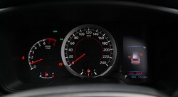
Toyota Corolla Cross: Vehicle status information and indicators
 The intricate workings of the information systems and instrument panel of your car are explained in detail in this section. This information is a valuable resource for drivers since it offers thorough explanations and direction on a range of vehicle maintenance and monitoring topics.
This chapter's core is a thorough dissection of the instrument panel, explaining the role and function of every light that illuminates your car's interior as well as every indicator and instrument. This chapter aims to give drivers the knowledge they need to effectively interpret and respond to their vehicle's condition in real time, from understanding the meaning of each symbol to knowing the implications of warning lights that signal problems like low fuel, abnormal tire pressure, or engine trouble.
This section delves into the topic of maintenance reminders, examining the underlying mechanics and providing explicit guidance on how to respond to or reset them following a service. This guarantees that owners may continue to be proactive in adhering to suggested maintenance plans, thus increasing the Corolla Cross's lifespan and functionality.
- Warning lights and indicators
- Gauges and meters (4.2-inch display)
- Gauges and meters (7-inch display)
- Multi-information display (4.2-inch display)
- Display and menu icons
- Changing the meter display
- Content of driving information
- Driving support system information display
- Vehicle information display
- Settings display
- Stop & Start system information
- Multi-information display (7-inch display)
- Display and menu icons
- Changing the meter display
- Driving support system information display
- Vehicle information display
- Settings display
- Suggestion function (if equipped)
- Fuel consumption information


