Toyota Corolla Cross: Shift Paddle Switch Circuit
DESCRIPTION
Moving the shift lever to S enables the shift range to be selected. The shift range can be selected by operating the "+" or "-" shift paddle switch.
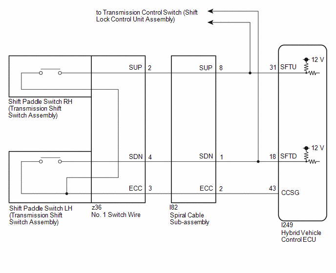
WIRING DIAGRAM
CAUTION / NOTICE / HINT
NOTICE:
After turning the ignition switch off, waiting time may be required before disconnecting the cable from the negative (-) auxiliary battery terminal. Therefore, make sure to read the disconnecting the cable from the negative (-) auxiliary battery terminal notices before proceeding with work.
Click here .gif)
PROCEDURE
|
1. | READ VALUE USING GTS (SPORTS SHIFT UP SIGNAL, SPORTS SHIFT DOWN SIGNAL) |
(a) Read the values displayed on the GTS.
Powertrain > Hybrid Control > Data List|
Tester Display |
|---|
|
Sports Shift UP Signal |
|
Sports Shift DOWN Signal |
| Result |
Proceed to |
|---|---|
| The display changes according to the shift paddle switch (transmission shift switch assembly) operation. |
A |
| The display does not change according to the shift paddle switch (transmission shift switch assembly) operation. |
B |
(b) Turn the ignition switch off.
| A | .gif) | CHECK FOR INTERMITTENT PROBLEMS |
|
.gif)
|
2. | CHECK HARNESS AND CONNECTOR (SHIFT PADDLE SWITCH CIRCUIT) |
(a) Disconnect the hybrid vehicle control ECU connector.
(b) Disconnect the transmission control switch (shift lock control unit assembly) connector.
(c) Measure the resistance according to the value(s) in the table below when the shift paddle switch (transmission shift switch assembly) is moved to each position.
Standard Resistance:
|
Tester Connection | Condition |
Specified Condition |
|---|---|---|
|
I249-31 (SFTU) - I249-43 (CCSG) |
Shift paddle switch RH (+) operated |
13 Ω or less |
|
I249-18 (SFTD) - I249-43 (CCSG) |
Shift paddle switch LH (-) operated |
13 Ω or less |
|
I249-31 (SFTU) - I249-43 (CCSG) |
Shift paddle switch RH (+) not operated |
10 kΩ or higher |
|
I249-18 (SFTD) - I249-43 (CCSG) |
Shift paddle switch LH (-) not operated |
10 kΩ or higher |
(d) Reconnect the transmission control switch (shift lock control unit assembly) connector.
(e) Reconnect the hybrid vehicle control ECU connector.
| OK | | REPLACE HYBRID VEHICLE CONTROL ECU |
|
|
3. | CHECK HARNESS AND CONNECTOR (SPIRAL CABLE SUB-ASSEMBLY - HYBRID VEHICLE CONTROL ECU) |
(a) Disconnect the hybrid vehicle control ECU connector.
(b) Disconnect the spiral cable with sensor sub-assembly connector.
(c) Measure the resistance according to the value(s) in the table below.
Standard Resistance:
|
Tester Connection | Condition |
Specified Condition |
|---|---|---|
|
I249-31 (SFTU) - I82-8 (SUP) |
Always | Below 1 Ω |
|
I249-18 (SFTD) - I82-1 (SDN) |
Always | Below 1 Ω |
|
I249-43 (CCSG) - I82-2 (ECC) |
Always | Below 1 Ω |
|
I249-31 (SFTU) or I82-8 (SUP) - Body ground |
Always | 10 kΩ or higher |
|
I249-18 (SFTD) or I82-1 (SDN) - Body ground |
Always | 10 kΩ or higher |
|
249-43 (CCSG) or I82-2 (ECC) - Body ground |
Always | 10 kΩ or higher |
(d) Reconnect the spiral cable with sensor sub-assembly connector.
(e) Reconnect the hybrid vehicle control ECU connector.
| NG | | REPAIR OR REPLACE HARNESS OR CONNECTOR |
|
|
4. | INSPECT SPIRAL CABLE SUB-ASSEMBLY |
(a) Inspect the spiral cable sub-assembly.
Click here
| NG | | REPLACE SPIRAL CABLE SUB-ASSEMBLY |
|
|
5. | INSPECT SHIFT PADDLE SWITCH LH (TRANSMISSION SHIFT SWITCH ASSEMBLY) |
(a) Inspect the shift paddle switch LH (transmission shift switch assembly).
Click here
| NG | | REPLACE SHIFT PADDLE SWITCH LH (TRANSMISSION SHIFT SWITCH ASSEMBLY) |
|
|
6. | INSPECT SHIFT PADDLE SWITCH RH (TRANSMISSION SHIFT SWITCH ASSEMBLY) |
(a) Inspect the shift paddle switch RH (transmission shift switch assembly).
Click here
| NG | | REPLACE SHIFT PADDLE SWITCH RH (TRANSMISSION SHIFT SWITCH ASSEMBLY) |
|
|
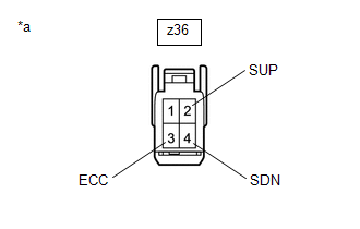
7. | INSPECT NO. 1 SWITCH WIRE |
(a) Disconnect the No. 1 switch wire connector.
| (b) Measure the resistance according to the value(s) in the table below. Standard Resistance:
|
|
(c) Reconnect the No. 1 switch wire connector.
| OK | | CHECK FOR INTERMITTENT PROBLEMS |
| NG | | REPLACE NO. 1 SWITCH WIRE |


