Toyota Corolla Cross: Drive Mode Select Switch Circuit
DESCRIPTION
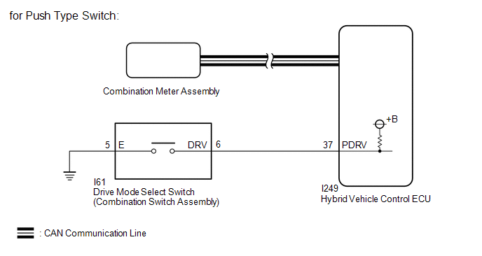
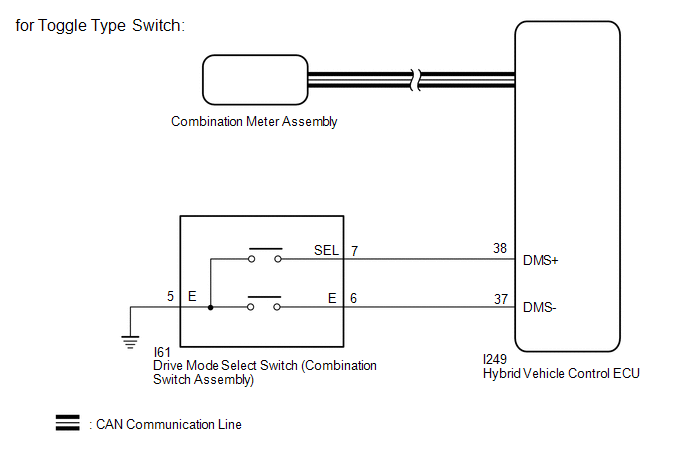
When the drive mode select switch (combination switch assembly) is operated, a switch signal is sent to the hybrid vehicle control ECU and the hybrid vehicle control ECU changes the drive mode.
WIRING DIAGRAM
PROCEDURE
|
1. | READ VALUE USING GTS (CAN BUS CHECK) |
Click here .gif)
|
Result | Proceed to |
|---|---|
|
All of the ECUs and sensors that are currently connected to the CAN communication system are displayed |
A |
| None of the ECUs and sensors that are currently connected to the CAN communication system are displayed, or some of them are not displayed |
B |
| B | .gif) | GO TO CAN COMMUNICATION SYSTEM |
|
.gif)
|
2. | CHECK DTC OUTPUT (HEALTH CHECK) |
Click here
|
Result | Proceed to |
|---|---|
|
No DTCs are output |
A |
| DTCs are output |
B |
| B | | GO TO DTC CHART |
|
|
3. | CHECK DRIVE MODE STATUS |
(a) Turn the ignition switch to ON.
(b) Operate the drive mode select switch (combination switch assembly) to change the drive mode.
(c) Check that the drive mode indicator is displayed on the multi-information display and changes according to the selected drive mode.
|
Result | Proceed to |
|---|---|
|
The display changes according to the drive mode select switch operation |
A |
| The display does not change according to the drive mode select switch operation (for Push Type Switch) |
B |
| The display does not change according to the drive mode select switch operation (for Toggle Type Switch) |
C |
(d) Turn the ignition switch off.
| A | | GO TO PROBLEM SYMPTOMS TABLE |
| C | | GO TO STEP 8 |
|
|
4. | READ VALUE USING GTS (POWERTRAIN DRIVE MODE SWITCH) |
(a) Read the value displayed on the GTS.
Powertrain > Hybrid Control > Data List|
Tester Display |
|---|
|
Powertrain Drive Mode Switch |
|
Result | Proceed to |
|---|---|
|
The display changes according to the drive mode select switch operation |
A |
| Other than above |
B |
(b) Turn the ignition switch off.
| A | | CHECK METER / GAUGE SYSTEM |
|
|
5. | INSPECT DRIVE MODE SELECT SWITCH (COMBINATION SWITCH ASSEMBLY) |
Click here
| NG | | REPLACE COMBINATION SWITCH ASSEMBLY |
|
|
6. | CHECK HARNESS AND CONNECTOR (DRIVE MODE SELECT SWITCH (COMBINATION SWITCH ASSEMBLY) - BODY GROUND) |
(a) Disconnect the drive mode select switch (combination switch assembly) connector.
(b) Measure the resistance according to the value(s) in the table below.
Standard Resistance:
|
Tester Connection | Condition |
Specified Condition |
|---|---|---|
|
I61-5 (E) - Body ground |
Always | Below 1 Ω |
(c) Reconnect the drive mode select switch (combination switch assembly) connector.
| NG | | REPAIR OR REPLACE HARNESS OR CONNECTOR |
|
|
7. | CHECK HARNESS AND CONNECTOR (HYBRID VEHICLE CONTROL ECU - DRIVE MODE SELECT SWITCH (COMBINATION SWITCH ASSEMBLY)) |
(a) Disconnect the hybrid vehicle control ECU connector.
(b) Disconnect the drive mode select switch (combination switch assembly) connector.
(c) Measure the resistance according to the value(s) in the table below.
Standard Resistance:
|
Tester Connection | Condition |
Specified Condition |
|---|---|---|
|
I249-37 (PDRV) - I61-6 (DRV) |
Always | Below 1 Ω |
|
I249-37 (PDRV) or I61-6 (DRV) - Body ground |
Always | 10 kΩ or higher |
(d) Reconnect the drive mode select switch (combination switch assembly) connector.
(e) Reconnect the hybrid vehicle control ECU connector.
| OK | | REPLACE HYBRID VEHICLE CONTROL ECU |
| NG | | REPAIR OR REPLACE HARNESS OR CONNECTOR |
|
8. | READ VALUE USING GTS (DRIVE MODE SWITCH) |
(a) Read the value displayed on the GTS.
Powertrain > Hybrid Control > Data List|
Tester Display |
|---|
|
Drive Mode Switch- |
|
Drive Mode Switch+ |
|
Result | Proceed to |
|---|---|
|
The display changes according to the drive mode select switch operation |
A |
| Other than above |
B |
(b) Turn the ignition switch off.
| A | | CHECK METER / GAUGE SYSTEM |
|
|
9. | INSPECT DRIVE MODE SELECT SWITCH (COMBINATION SWITCH ASSEMBLY) |
Click here
| NG | | REPLACE COMBINATION SWITCH ASSEMBLY |
|
|
10. | CHECK HARNESS AND CONNECTOR (DRIVE MODE SELECT SWITCH (COMBINATION SWITCH ASSEMBLY) - BODY GROUND) |
(a) Disconnect the drive mode select switch (combination switch assembly) connector.
(b) Measure the resistance according to the value(s) in the table below.
Standard Resistance:
|
Tester Connection | Condition |
Specified Condition |
|---|---|---|
|
I61-5 (E) - Body ground |
Always | Below 1 Ω |
(c) Reconnect the drive mode select switch (combination switch assembly) connector.
| NG | | REPAIR OR REPLACE HARNESS OR CONNECTOR |
|
|
11. | CHECK HARNESS AND CONNECTOR (HYBRID VEHICLE CONTROL ECU - DRIVE MODE SELECT SWITCH (COMBINATION SWITCH ASSEMBLY)) |
(a) Disconnect the hybrid vehicle control ECU connector.
(b) Disconnect the drive mode select switch (combination switch assembly) connector.
(c) Measure the resistance according to the value(s) in the table below.
Standard Resistance:
|
Tester Connection | Condition |
Specified Condition |
|---|---|---|
|
I249-37 (DMS-) - I61-6 (E) |
Always | Below 1 Ω |
|
I249-38 (DMS+) - I61-7 (SEL) |
Always | Below 1 Ω |
|
I249-37 (DMS-) or I61-6 (E) - Body ground |
Always | 10 kΩ or higher |
|
I249-38 (DMS+) or I61-7 (SEL) - Body ground |
Always | 10 kΩ or higher |
(d) Reconnect the drive mode select switch (combination switch assembly) connector.
(e) Reconnect the hybrid vehicle control ECU connector.
| OK | | REPLACE HYBRID VEHICLE CONTROL ECU |
| NG | | REPAIR OR REPLACE HARNESS OR CONNECTOR |


