Toyota Corolla Cross: Engine Coolant Temperature Sensor 1 Circuit Short to Battery or Open (P011515)
DESCRIPTION
Refer to DTC P011511.
Click here
.gif)
HINT:
When DTC P011515 is stored, the ECM enters fail-safe mode. During fail-safe mode, the engine coolant temperature is estimated to be 80°C (176°F) by the ECM. Fail-safe mode continues until a pass condition is detected.
|
DTC No. | Detection Item |
DTC Detection Condition | Trouble Area |
MIL | Note |
|---|---|---|---|---|---|
|
P011515 | Engine Coolant Temperature Sensor 1 Circuit Short to Battery or Open |
Diagnosis condition:
Abnormal condition:
Malfunction time:
Trip logic:
Detection conditions:
Sensors/components used for detection:
|
| Comes on |
|
HINT:
When this DTC is output, check the engine coolant temperature in the Data List. Enter the following menus: Powertrain / Engine / Data List / Coolant Temperature.
|
DTC No. | Coolant Temperature |
Malfunction |
|---|---|---|
| P011515 |
-40°C (-40°F) |
|
If the Data List values is normal it may be due to a temporary recovery from the malfunction condition. Check for intermittent problems.
Click here
MONITOR DESCRIPTION
When the ignition switch is turned ON and the output voltage of the engine coolant temperature sensor is higher than 4.91 V for 0.5 seconds or more, the ECM determines that the engine coolant temperature sensor circuit is malfunctioning and illuminates the MIL and stores a DTC.
MONITOR STRATEGY
|
Related DTCs | P0118: Engine coolant temperature sensor range check (high voltage) |
|
Required Sensors/Components (Main) | Engine coolant temperature sensor |
|
Required Sensors/Components (Related) | - |
|
Frequency of Operation | Continuous |
|
Duration | 0.5 seconds |
| MIL Operation |
Immediate |
| Sequence of Operation |
None |
TYPICAL ENABLING CONDITIONS
|
Monitor runs whenever the following DTCs are not stored |
None |
| All of the following conditions are met |
- |
| Auxiliary battery voltage |
8 V or higher |
| Ignition switch |
ON |
| Starter | Off |
TYPICAL MALFUNCTION THRESHOLDS
|
Engine coolant temperature sensor voltage [Engine coolant temperature] |
Higher than 4.91 V [Less than -59°C (-74°F)] |
CONFIRMATION DRIVING PATTERN
Refer to DTC P011511.
Click here
WIRING DIAGRAM
Refer to DTC P011511.
Click here
CAUTION / NOTICE / HINT
HINT:
Read Freeze Frame Data using the GTS. The ECM records vehicle and driving condition information as Freeze Frame Data the moment a DTC is stored. When troubleshooting, Freeze Frame Data can help determine if the vehicle was moving or stationary, if the engine was warmed up or not, if the air fuel ratio was lean or rich, and other data from the time the malfunction occurred.
PROCEDURE
| 1. |
CHECK TERMINAL VOLTAGE (ENGINE COOLANT TEMPERATURE SENSOR) |
|
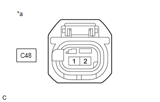
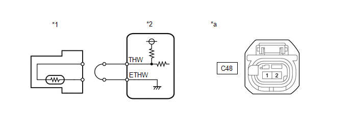
*a | Front view of wire harness connector (to Engine Coolant Temperature Sensor) |
(a) Disconnect the engine coolant temperature sensor connector.
(b) Turn the ignition switch to ON.
(c) Measure the voltage according to the value(s) in the table below.
Standard Voltage:
|
Tester Connection | Condition |
Specified Condition |
|---|---|---|
|
C48-2 - Body ground | Ignition switch ON |
0 to 5.5 V |
| NG | .gif) | GO TO STEP 4 |
|
.gif)
| 2. |
READ VALUE USING GTS (COOLANT TEMPERATURE) |
|
*1 | Engine Coolant Temperature Sensor |
*2 | ECM |
|
*a | Front view of wire harness connector (to Engine Coolant Temperature Sensor) |
- | - |
(a) Disconnect the engine coolant temperature sensor connector.
(b) Connect terminals 1 and 2 of the engine coolant temperature sensor connector on the wire harness side.
(c) Enter the following menus.
Powertrain > Engine > Data List|
Tester Display |
|---|
| Coolant Temperature |
(d) According to the display on the GTS, read the Data List.
OK:
|
GTS Display | Specified Condition |
|---|---|
|
Coolant Temperature | 140°C (284°F) |
HINT:
Perform "Inspection After Repair" after replacing the engine coolant temperature sensor.
Click here
| OK | | REPLACE ENGINE COOLANT TEMPERATURE SENSOR
|
|
| 3. |
CHECK HARNESS AND CONNECTOR (ENGINE COOLANT TEMPERATURE SENSOR - ECM) |
(a) Disconnect the engine coolant temperature sensor connector.
(b) Disconnect the ECM connector.
(c) Measure the resistance according to the value(s) in the table below.
Standard Resistance:
|
Tester Connection | Condition |
Specified Condition |
|---|---|---|
|
C48-2 - C76-125 (THW) |
Always | Below 1 Ω |
|
C48-1 - C76-124 (ETHW) |
Always | Below 1 Ω |
| OK | | REPLACE ECM
|
| NG | | REPAIR OR REPLACE HARNESS OR CONNECTOR |
| 4. |
CHECK HARNESS AND CONNECTOR (ENGINE COOLANT TEMPERATURE SENSOR - ECM) |
(a) Disconnect the engine coolant temperature sensor connector.
(b) Disconnect the ECM connector.
(c) Measure the resistance according to the value(s) in the table below.
Standard Resistance:
|
Tester Connection | Condition |
Specified Condition |
|---|---|---|
|
C48-2 or C76-125 (THW) - Other terminals |
Always | 10 kΩ or higher |
| OK | | REPLACE ECM
|
| NG | | REPAIR OR REPLACE HARNESS OR CONNECTOR |
READ NEXT:
 Engine Coolant Temperature Sensor 1 Signal Stuck in Range (P01152A)
DESCRIPTION Refer to DTC P011511. Click here
DTC No. Detection Item
DTC Detection Condition Trouble Area
MIL Note
P01152A Engine Coolant Temperature Sensor 1 Signal
Throttle / Pedal Position Sensor / Switch "A" Circuit Short to Ground (P012011)
DESCRIPTION The throttle position sensor is built into the throttle body with motor assembly and detects the opening angle of the throttle valve. This sensor is a non-contact type sensor. It uses Hall
Throttle / Pedal Position Sensor / Switch "A" Circuit Short to Battery or Open (P012015)
DESCRIPTION Refer to DTC P012011. Click here
DTC No. Detection Item
DTC Detection Condition Trouble Area
MIL Note
P012015 Throttle / Pedal Position Sensor / Switch
SEE MORE:
 Registration
REGISTRATION PROCEDURE 1. REPAIR INSTRUCTION
CAUTION: As weak radio waves are emitted from the electrical key transmitter sub-assembly, if a pacemaker is being used, be sure to read the pacemaker instruction manual and the following.
People with implantable cardiac pacemakers, cardiac resynch
Brake Hold Switch
Inspection
INSPECTION
PROCEDURE
1. INSPECT BRAKE HOLD SWITCH (ELECTRIC PARKING BRAKE SWITCH ASSEMBLY)
(a) Check the resistance.
(1) Measure the resistance according to the value(s) in the
table below.
Standard Resistance:
Tester Connection
