Toyota Corolla Cross: Fuel Rail Pressure Sensor (Low) Circuit Short to Ground (P107A11)
DESCRIPTION
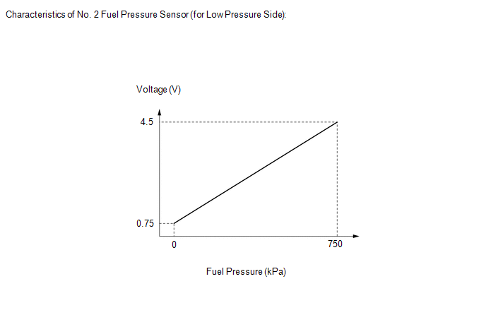
The No. 2 fuel pressure sensor (for low pressure side) replaces the fuel pressure with electrical signals and outputs them to the ECM. The ECM controls the optimal fuel pressure for the operation conditions to reduce the fuel pump power consumption and improve fuel economy.
|
DTC No. | Detection Item |
DTC Detection Condition | Trouble Area |
MIL | Note |
|---|---|---|---|---|---|
|
P107A11 | Fuel Rail Pressure Sensor (Low) Circuit Short to Ground |
Diagnosis condition:
Abnormal condition:
Malfunction time:
Trip logic:
Detection conditions:
Sensors/components used for detection:
|
| Comes on |
|
HINT:
When this DTC is output, check the fuel pressure (for low pressure side) in the Data List. Enter the following menus: Powertrain / Engine / Data List / Fuel Pressure (Low) / Fuel Pressure 2.
|
DTC No. | Fuel Pressure (Low) / Fuel Pressure 2 |
Malfunction |
|---|---|---|
| P107A11 |
Approximately 0 kPag |
|
If the Data List values is normal it may be due to a temporary recovery from the malfunction condition. Check for intermittent problems.
Click here .gif)
MONITOR DESCRIPTION
2 seconds or more after the engine has started, if the output voltage of the No. 2 fuel pressure sensor (for low pressure side) is less than 0.43 V for 3 seconds or more, the ECM determines that the No. 2 fuel pressure sensor (for low pressure side) circuit is malfunctioning and illuminates the MIL and stores a DTC.
MONITOR STRATEGY
|
Related DTCs | P107C: Fuel rail pressure sensor range check (Low voltage) |
|
Required Sensors/Components (Main) | No. 2 fuel pressure sensor (for low pressure side) |
|
Required Sensors/Components (Related) |
- |
| Frequency of Operation |
Continuous |
| Duration |
3 seconds |
| MIL Operation |
Immediate |
| Sequence of Operation |
None |
TYPICAL ENABLING CONDITIONS
|
Monitor runs whenever the following DTCs are not stored |
None |
| All of the following conditions are met |
- |
| Auxiliary battery voltage |
8 V or higher |
| Ignition switch |
ON |
| Starter |
Off |
| Time after engine start |
2 seconds or more |
TYPICAL MALFUNCTION THRESHOLDS
|
Fuel rail pressure sensor voltage | Less than 0.43 V |
CONFIRMATION DRIVING PATTERN
HINT:
- After repair has been completed, clear the DTC and then check that the vehicle has returned to normal by performing the following All Readiness check procedure.
Click here
- When clearing the permanent DTCs, refer to the "CLEAR PERMANENT DTC" procedure.
Click here
- Connect the GTS to the DLC3.
- Turn the ignition switch to ON.
- Turn the GTS on.
- Clear the DTCs (even if no DTCs are stored, perform the clear DTC procedure).
- Turn the ignition switch off and wait for at least 30 seconds.
- Start the engine.
- Idle the engine for 10 seconds or more [A].
- Turn the GTS on.
- Enter the following menus: Powertrain / Engine / Trouble Codes [B].
- Read the pending DTCs.
HINT:
- If a pending DTC is output, the system is malfunctioning.
- If a pending DTC is not output, perform the following procedure.
- Enter the following menus: Powertrain / Engine / Utility / All Readiness.
- Proceed to the next screen and enter the DTC to be checked.
- Check the DTC judgment result.
GTS Display
Description
NORMAL
- DTC judgment completed
- System normal
ABNORMAL
- DTC judgment completed
- System abnormal
INCOMPLETE
- DTC judgment not completed
- Perform driving pattern after confirming DTC enabling conditions
HINT:
- If the judgment result is NORMAL, the system is normal.
- If the judgment result is ABNORMAL, the system has a malfunction.
- If the judgment result is INCOMPLETE, perform steps [A] through [B] again.
- [A] to [B]: Normal judgment procedure.
The normal judgment procedure is used to complete DTC judgment and also used when clearing permanent DTCs.
- When clearing the permanent DTCs, do not disconnect the cable from the auxiliary battery terminal or attempt to clear the DTCs during this procedure, as doing so will clear the universal trip and normal judgment histories.
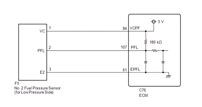
WIRING DIAGRAM
CAUTION / NOTICE / HINT
HINT:
Read Freeze Frame Data using the GTS. The ECM records vehicle and driving condition information as Freeze Frame Data the moment a DTC is stored. When troubleshooting, Freeze Frame Data can help determine if the vehicle was moving or stationary, if the engine was warmed up or not, if the air fuel ratio was lean or rich, and other data from the time the malfunction occurred.
PROCEDURE
| 1. |
READ VALUE USING GTS (FUEL PRESSURE (LOW) / FUEL PRESSURE 2) |
HINT:
Make sure that the connector is properly connected. If it is not, securely connect it and check for DTCs again.
(a) Enter the following menus.
Powertrain > Engine > Data List|
Tester Display |
|---|
| Fuel Pressure (Low) / Fuel Pressure 2 |
(b) Turn the ignition switch off.
(c) Disconnect the No. 2 fuel pressure sensor (for low pressure side) connector.
(d) Turn the ignition switch to ON.
(e) Enter the following menus.
Powertrain > Engine > Data List|
Tester Display |
|---|
| Fuel Pressure (Low) / Fuel Pressure 2 |
(f) Compare the Data List value when the connector is connected and when the connector is not connected.
|
Result | Proceed to |
|---|---|
|
The value of Fuel Pressure (Low) / Fuel Pressure 2 changes |
A |
| The value of Fuel Pressure (Low) / Fuel Pressure 2 does not change |
B |
| B |
.gif) | GO TO STEP 4 |
|
.gif)
| 2. |
CHECK TERMINAL VOLTAGE (NO. 2 FUEL PRESSURE SENSOR (FOR LOW PRESSURE SIDE)) |
|
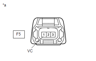
*a | Front view of wire harness connector (to No. 2 Fuel Pressure Sensor (for Low Pressure Side)) |
(a) Disconnect the No. 2 fuel pressure sensor (for low pressure side) connector.
(b) Turn the ignition switch to ON.
(c) Measure the voltage according to the value(s) in the table below.
Standard Voltage:
|
Tester Connection | Condition |
Specified Condition |
|---|---|---|
|
F5-1 (VC) - Body ground |
Ignition switch ON | 4.5 to 5.5 V |
HINT:
Perform "Inspection After Repair" after replacing the No. 2 fuel pressure sensor (for low pressure side).
Click here
| OK | | REPLACE NO. 2 FUEL PRESSURE SENSOR (FOR LOW PRESSURE SIDE)
|
|
| 3. |
CHECK HARNESS AND CONNECTOR (NO. 2 FUEL PRESSURE SENSOR (FOR LOW PRESSURE SIDE) - ECM) |
(a) Disconnect the No. 2 fuel pressure sensor (for low pressure side) connector.
(b) Disconnect the ECM connector.
(c) Measure the resistance according to the value(s) in the table below.
Standard Resistance:
|
Tester Connection | Condition |
Specified Condition |
|---|---|---|
|
F5-1 (VC) - C76-84 (VCPF) |
Always | Below 1 Ω |
| OK | | REPLACE ECM
|
| NG | | REPAIR OR REPLACE HARNESS OR CONNECTOR |
| 4. |
CHECK TERMINAL VOLTAGE (NO. 2 FUEL PRESSURE SENSOR (FOR LOW PRESSURE SIDE)) |
|
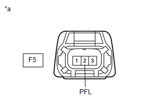
*a | Front view of wire harness connector (to No. 2 Fuel Pressure Sensor (for Low Pressure Side)) |
(a) Disconnect the No. 2 fuel pressure sensor (for low pressure side) connector.
(b) Turn the ignition switch to ON.
(c) Measure the voltage according to the value(s) in the table below.
Standard Voltage:
|
Tester Connection | Condition |
Specified Condition |
|---|---|---|
|
F5-2 (PFL) - Body ground |
Ignition switch ON | 4.4 to 5.6 V |
| OK | | REPLACE ECM
|
|
| 5. |
CHECK HARNESS AND CONNECTOR (NO. 2 FUEL PRESSURE SENSOR (FOR LOW PRESSURE SIDE) - ECM) |
(a) Disconnect the No. 2 fuel pressure sensor (for low pressure side) connector.
(b) Disconnect the ECM connector.
(c) Measure the resistance according to the value(s) in the table below.
Standard Resistance:
|
Tester Connection | Condition |
Specified Condition |
|---|---|---|
|
F5-2 (PFL) or C76-107 (PFL) - Body ground and other terminals |
Always | 10 kΩ or higher |
| OK | | REPLACE ECM
|
| NG | | REPAIR OR REPLACE HARNESS OR CONNECTOR |


