Toyota Corolla Cross: Control Module Internal Temperature Sensor/Intake Air Temperature Sensor Signal Compare Failure (P111C62)
DESCRIPTION
The engine has an ECM internal temperature sensor and intake air temperature sensor.
The resistance of a thermistor within the ECM internal temperature sensor and intake air temperature sensor increases as the temperature decreases and decreases as the temperature increases.
The voltage monitored by the ECM changes in accordance with the change in the resistance of the thermistor.
The ECM performs control based on these voltages.
|
DTC No. | Detection Item |
DTC Detection Condition | Trouble Area |
MIL | Note |
|---|---|---|---|---|---|
|
P111C62 | Control Module Internal Temperature Sensor/Intake Air Temperature Sensor Signal Compare Failure |
All of the following conditions are met (2 trip detection logic):
|
| Comes on |
|
|
DTC No. | Data List |
|---|---|
|
P111C62 | Intake Air Temperature |
|
Ambient Temperature |
HINT:
- Waiting is required to prevent the temperature of the engine from affecting the readings. If the engine has been operated recently, it is not possible to accurately compare the readings.
- For diagnosis, in order to duplicate the detection conditions of the DTC, it is necessary to park the vehicle for 7 hours. Parking the vehicle for 7 hours ensures that the actual temperature of the ECM internal temperature and intake air temperature (for mass airflow meter sub-assembly) are very similar. When the vehicle has been parked for less than 7 hours, differences in the readings may exist, but this does not necessarily indicate a fault.
MONITOR DESCRIPTION
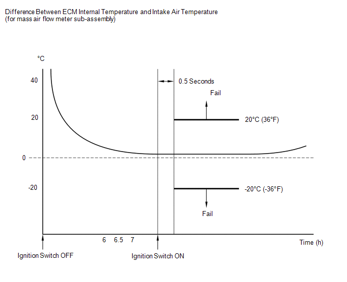
6, 6.5 and 7 hours after the engine has stopped, the ECM monitors the voltage of the ECM internal temperature sensor and intake air temperature sensor.
If the difference between the readings of the ECM internal temperature and intake air temperature is more than 20°C (36°F), the ECM determines that there is a malfunction in the ECM internal temperature sensor circuit or intake air temperature sensor circuit and stores a DTC and illuminates the MIL.
MONITOR STRATEGY
|
Related DTCs | P111C: Intake air temperature / engine control module internal temperature sensor correlation |
|
Required Sensors/Components (Main) | Intake air temperature sensor Engine control module internal temperature sensor |
|
Required Sensors/Components (Related) |
- |
| Frequency of Operation |
Once per driving cycle |
| Duration |
- |
| MIL Operation |
2 driving cycles |
| Sequence of Operation |
None |
TYPICAL ENABLING CONDITIONS
|
All of the following conditions are met |
- |
| Ignition switch |
Off |
| Engine |
Stall |
| Soak time |
6, 6.5 and 7 hours |
| One of the following conditions is met |
(a) or (b) |
| (a) Engine control module internal temperature |
-10°C (14°F) or higher |
|
(b) Intake air temperature |
-10°C (14°F) or higher |
|
Engine control module internal temperature sensor circuit fail (P06AD, P06AE) (Pending + MIL) |
Not detected |
|
Intake air temperature sensor circuit fail (P0112, P0113) (Pending + MIL) |
Not detected |
|
Soak timer fail (P2610) (Pending + MIL) |
Not detected |
|
Auxiliary battery voltage |
8 V or higher |
|
Starter | Off |
|
Time after ECM power on |
0.5 seconds or more |
TYPICAL MALFUNCTION THRESHOLDS
|
Deviated engine control module internal temperature and intake air temperature |
Less than -20°C (-36°F), or higher than 20°C (36°F) |
CONFIRMATION DRIVING PATTERN
HINT:
- After repair has been completed, clear the DTC and then check that the vehicle has returned to normal by performing the following All Readiness check procedure.
Click here
.gif)
- When clearing the permanent DTCs, refer to the "CLEAR PERMANENT DTC" procedure.
Click here
- Connect the GTS to the DLC3.
- Turn the ignition switch to ON [A].
- Turn the GTS on.
- Clear the DTCs (even if no DTCs are stored, perform the clear DTC procedure).
- Turn the ignition switch off.
- With the engine stopped, leave the vehicle as is for 7.5 hours or more [B].
- Turn the ignition switch to ON.
- Turn the GTS on.
- Wait 1 second [C].
- Enter the following menus: Powertrain / Engine / Trouble Codes [D].
- Read the pending DTCs.
HINT:
- If a pending DTC is output, the system is malfunctioning.
- If a pending DTC is not output, perform the following procedure.
- Enter the following menus: Powertrain / Engine / Utility / All Readiness.
- Input the DTC: P111C62.
- Check the DTC judgment result.
GTS Display
Description
NORMAL
- DTC judgment completed
- System normal
ABNORMAL
- DTC judgment completed
- System abnormal
INCOMPLETE
- DTC judgment not completed
- Perform driving pattern after confirming DTC enabling conditions
HINT:
- If the judgment result is NORMAL, the system is normal.
- If the judgment result is ABNORMAL, the system is malfunctioning.
- If the judgment result is INCOMPLETE, perform steps [B] through [D] again.
- [B] to [D]: Normal judgment procedure.
The normal judgment procedure is used to complete DTC judgment and also used when clearing permanent DTCs.
- When clearing the permanent DTCs, do not disconnect the cable from the auxiliary battery terminal or attempt to clear the DTCs during this procedure, as doing so will clear the universal trip and normal judgment histories.
CAUTION / NOTICE / HINT
HINT:
Read Freeze Frame Data using the GTS. The ECM records vehicle and driving condition information as Freeze Frame Data the moment a DTC is stored. When troubleshooting, Freeze Frame Data can help determine if the vehicle was moving or stationary, if the engine was warmed up or not, if the air fuel ratio was lean or rich, and other data from the time the malfunction occurred.
PROCEDURE
| 1. |
CHECK ANY OTHER DTCS OUTPUT (IN ADDITION TO P111C62) |
(a) Read the DTCs.
Powertrain > Engine > Trouble Codes|
Result | Proceed to |
|---|---|
|
DTC P111C62 is output |
A |
| DTC P111C62 and other DTCs are output |
B |
HINT:
If any DTCs other than P111C62 are output, troubleshoot those DTCs first.
(b) Record the freeze frame data.
| B | .gif) |
GO TO DTC CHART |
|
.gif)
| 2. |
CHECK FREEZE FRAME DATA (INTAKE AIR TEMPERATURE AND AMBIENT TEMPERATURE) |
(a) Using the GTS, read the values displayed in the freeze frame data recorded in step 1.
Powertrain > Engine|
Tester Display |
|---|
| Intake Air Temperature |
|
Ambient Temperature |
(b) Read the value displayed on the GTS.
Standard:
Difference between the Intake Air Temperature and the Ambient Temperature is within 15°C (27°F).
HINT:
- When the engine is cold, the value of the intake air temperature, ECM internal temperature and ambient temperature should be approximately the same.
- Perform "Inspection After Repair" after replacing the mass air flow meter sub-assembly.
Click here
| OK | | REPLACE ECM
|
| NG | | REPLACE MASS AIR FLOW METER SUB-ASSEMBLY |
READ NEXT:
 Bank 1 Air-Fuel Ratio Imbalance (Port) (P11EA00,P11EC00-P11EF00,P219A00,P219C00-P219F00)
DESCRIPTION Refer to DTC P003012. Click here
Refer to DTC P030000. Click here
DTC No. Detection Item
DTC Detection Condition Trouble Area
MIL Note
P11EA00 Bank
High Pressure Fuel Pump Circuit Open (P123513)
DESCRIPTION The high-pressure direct injection fuel system consists of a spill control valve, check valve, fuel relief valve, fuel pressure sensor (for high pressure side), fuel pump assembly (for hig
Cold Start Fuel Injection Control Performance #1 (P128300-P128600)
DESCRIPTION To improve emissions immediately after a cold start, cold start multi pulse fuel injection control is performed which divides a single pulse of the direct fuel injector into several smalle
SEE MORE:
 Problem Symptoms Table
PROBLEM SYMPTOMS TABLE
HINT:
Use the table below to help determine the cause of problem symptoms. If multiple suspected areas are listed, the potential causes of the symptoms are listed in order of probability in the "Suspected Area" column of the table. Check each symptom by checking the susp
Taillight Relay Circuit
DESCRIPTION The main body ECU (multiplex network body ECU) controls the taillight and license plate light. WIRING DIAGRAM
for LED Type Parking Light
for Bulb Type Parking Light
CAUTION / NOTICE / HINT
NOTICE:
First perform the communication function inspections in How to Proceed with Trou
