Toyota Corolla Cross: Fuel Rail Pressure Sensor (Low) Circuit Short to Battery or Open (P107A15)
DESCRIPTION
Refer to DTC P107A11.
Click here
.gif)
|
DTC No. | Detection Item |
DTC Detection Condition | Trouble Area |
MIL | Note |
|---|---|---|---|---|---|
|
P107A15 | Fuel Rail Pressure Sensor (Low) Circuit Short to Battery or Open |
Diagnosis condition:
Abnormal condition:
Malfunction time:
Trip logic:
Detection conditions:
Sensors/components used for detection:
|
| Comes on |
|
HINT:
When this DTC is output, check the fuel pressure (for low pressure side) in the Data List. Enter the following menus: Powertrain / Engine / Data List / Fuel Pressure (Low) / Fuel Pressure 2.
|
DTC No. | Fuel Pressure (Low) / Fuel Pressure 2 |
Malfunction |
|---|---|---|
| P107A15 |
Approximately 750 kPag or higher |
|
If the Data List values is normal it may be due to a temporary recovery from the malfunction condition. Check for intermittent problems.
Click here
MONITOR DESCRIPTION
When the ignition switch is turned ON and the output voltage of the No. 2 fuel pressure sensor (for low pressure side) is higher than 4.85 V for 3 seconds or more, the ECM determines that the No. 2 fuel pressure sensor (for low pressure side) circuit is malfunctioning and illuminates the MIL and stores a DTC
MONITOR STRATEGY
|
Related DTCs | P107D: Fuel rail pressure sensor range check (High voltage) |
|
Required Sensors/Components (Main) | No. 2 fuel pressure sensor (for low pressure side) |
|
Required Sensors/Components (Related) |
- |
| Frequency of Operation |
Continuous |
| Duration |
3 seconds |
| MIL Operation |
Immediate |
| Sequence of Operation |
None |
TYPICAL ENABLING CONDITIONS
|
Monitor runs whenever the following DTCs are not stored |
None |
| All of the following conditions are met |
- |
| Auxiliary battery voltage |
8 V or higher |
| Ignition switch |
ON |
| Starter |
Off |
TYPICAL MALFUNCTION THRESHOLDS
|
Fuel rail pressure sensor voltage | Higher than 4.85 V |
CONFIRMATION DRIVING PATTERN
HINT:
- After repair has been completed, clear the DTC and then check that the vehicle has returned to normal by performing the following All Readiness check procedure.
Click here
- When clearing the permanent DTCs, refer to the "CLEAR PERMANENT DTC" procedure.
Click here
- Connect the GTS to the DLC3.
- Turn the ignition switch to ON.
- Turn the GTS on.
- Clear the DTCs (even if no DTCs are stored, perform the clear DTC procedure).
- Turn the ignition switch off and wait for at least 30 seconds.
- Turn the ignition switch to ON [A].
- Turn the GTS on.
- Wait 10 seconds or more [B].
- Enter the following menus: Powertrain / Engine / Trouble Codes [C].
- Read the pending DTCs.
HINT:
- If a pending DTC is output, the system is malfunctioning.
- If a pending DTC is not output, perform the following procedure.
- Enter the following menus: Powertrain / Engine / Utility / All Readiness.
- Proceed to the next screen and enter the DTC to be checked.
- Check the DTC judgment result.
GTS Display
Description
NORMAL
- DTC judgment completed
- System normal
ABNORMAL
- DTC judgment completed
- System abnormal
INCOMPLETE
- DTC judgment not completed
- Perform driving pattern after confirming DTC enabling conditions
HINT:
- If the judgment result is NORMAL, the system is normal.
- If the judgment result is ABNORMAL, the system is malfunctioning.
- [A] to [C]: Normal judgment procedure.
The normal judgment procedure is used to complete DTC judgment and also used when clearing permanent DTCs.
- When clearing the permanent DTCs, do not disconnect the cable from the auxiliary battery terminal or attempt to clear the DTCs during this procedure, as doing so will clear the universal trip and normal judgment histories.
WIRING DIAGRAM
Refer to DTC P107A11.
Click here
CAUTION / NOTICE / HINT
HINT:
Read Freeze Frame Data using the GTS. The ECM records vehicle and driving condition information as Freeze Frame Data the moment a DTC is stored. When troubleshooting, Freeze Frame Data can help determine if the vehicle was moving or stationary, if the engine was warmed up or not, if the air fuel ratio was lean or rich, and other data from the time the malfunction occurred.
PROCEDURE
| 1. |
CHECK HARNESS AND CONNECTOR (NO. 2 FUEL PRESSURE SENSOR (FOR LOW PRESSURE SIDE) - BODY GROUND) |
HINT:
Make sure that the connector is properly connected. If it is not, securely connect it and check for DTCs again.
(a) Disconnect the No. 2 fuel pressure sensor (for low pressure side) connector.
(b) Measure the resistance according to the value(s) in the table below.
Standard Resistance:
|
Tester Connection | Condition |
Specified Condition |
|---|---|---|
|
F5-3 (E2) - Body ground |
Always | Below 1 Ω |
| NG | .gif) | GO TO STEP 7 |
|
.gif)
| 2. |
CHECK TERMINAL VOLTAGE (NO. 2 FUEL PRESSURE SENSOR (FOR LOW PRESSURE SIDE)) |
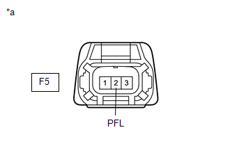
|
*a | Front view of wire harness connector (to No. 2 Fuel Pressure Sensor (for Low Pressure Side)) |
(a) Disconnect the No. 2 fuel pressure sensor (for low pressure side) connector.
(b) Turn the ignition switch to ON.
(c) Measure the voltage according to the value(s) in the table below.
Standard Voltage:
|
Tester Connection | Condition |
Specified Condition |
|---|---|---|
|
F5-2 (PFL) - Body ground |
Ignition switch ON | 4.4 to 5.6 V |
|
Result | Proceed to |
|---|---|
|
Higher than 5.6 V | A |
|
4.4 to 5.6 V | B |
|
Below 4.4 V | C |
| B |
| GO TO STEP 4 |
| C |
| GO TO STEP 6 |
|
| 3. |
CHECK HARNESS AND CONNECTOR (NO. 2 FUEL PRESSURE SENSOR (FOR LOW PRESSURE SIDE) - ECM) |
(a) Disconnect the No. 2 fuel pressure sensor (for low pressure side) connector.
(b) Disconnect the ECM connector.
(c) Measure the resistance according to the value(s) in the table below.
Standard Resistance:
|
Tester Connection | Condition |
Specified Condition |
|---|---|---|
|
F5-2 (PFL) or C76-107 (PFL) - Other terminals |
Always | 10 kΩ or higher |
| OK | | REPLACE ECM
|
| NG | | REPAIR OR REPLACE HARNESS OR CONNECTOR |
| 4. |
CHECK INTERNAL RESISTANCE (ECM) |
(a) Turn the ignition switch off.
(b) Disconnect the No. 2 fuel pressure sensor (for low pressure side) connector.
(c) Measure the resistance according to the value(s) in the table below.
Standard Resistance:
|
Tester Connection | Condition |
Specified Condition |
|---|---|---|
|
F5-1 (VC) - F5-2 (PFL) |
Ignition switch off | 171 to 189 kΩ |
HINT:
- As voltage is still supplied to the ECM after the ignition switch is turned off, this check cannot be performed correctly during the shut-down process.
- Perform "Inspection After Repair" after replacing the No. 2 fuel pressure sensor (for low pressure side).
Click here
| OK | | REPLACE NO. 2 FUEL PRESSURE SENSOR (FOR LOW PRESSURE SIDE)
|
|
| 5. |
CHECK HARNESS AND CONNECTOR (NO. 2 FUEL PRESSURE SENSOR (FOR LOW PRESSURE SIDE) - ECM) |
(a) Disconnect the No. 2 fuel pressure sensor (for low pressure side) connector.
(b) Disconnect the ECM connector.
(c) Measure the resistance according to the value(s) in the table below.
Standard Resistance:
|
Tester Connection | Condition |
Specified Condition |
|---|---|---|
|
F5-1 (VC) - F5-2 (PFL) or C76-84 (VCPF) - C76-107 (PFL) |
Always | 10 kΩ or higher |
| OK | | REPLACE ECM
|
| NG | | REPAIR OR REPLACE HARNESS OR CONNECTOR |
| 6. |
CHECK HARNESS AND CONNECTOR (NO. 2 FUEL PRESSURE SENSOR (FOR LOW PRESSURE SIDE) - ECM) |
(a) Disconnect the No. 2 fuel pressure sensor (for low pressure side) connector.
(b) Disconnect the ECM connector.
(c) Measure the resistance according to the value(s) in the table below.
Standard Resistance:
|
Tester Connection | Condition |
Specified Condition |
|---|---|---|
|
F5-2 (PFL) - C76-107 (PFL) |
Always | Below 1 Ω |
| OK | | REPLACE ECM
|
| NG | | REPAIR OR REPLACE HARNESS OR CONNECTOR |
| 7. |
CHECK HARNESS AND CONNECTOR (NO. 2 FUEL PRESSURE SENSOR (FOR LOW PRESSURE SIDE) - ECM) |
(a) Disconnect the No. 2 fuel pressure sensor (for low pressure side) connector.
(b) Disconnect the ECM connector.
(c) Measure the resistance according to the value(s) in the table below.
Standard Resistance:
|
Tester Connection | Condition |
Specified Condition |
|---|---|---|
|
F5-3 (E2) - C76-61 (EPFL) |
Always | Below 1 Ω |
| OK | | REPLACE ECM
|
| NG | | REPAIR OR REPLACE HARNESS OR CONNECTOR |
READ NEXT:
 Fuel Rail Pressure Sensor (Low) Signal Stuck in Range (P107A2A,P107A64)
DESCRIPTION Refer to DTC P107A11. Click here
DTC No. Detection Item
DTC Detection Condition Trouble Area
MIL Note
P107A2A Fuel Rail Pressure Sensor (Low) Signal Stu
Control Module Internal Temperature Sensor/Intake Air Temperature Sensor Signal Compare Failure (P111C62)
DESCRIPTION The engine has an ECM internal temperature sensor and intake air temperature sensor.
The resistance of a thermistor within the ECM internal temperature sensor and intake air temperature
Bank 1 Air-Fuel Ratio Imbalance (Port) (P11EA00,P11EC00-P11EF00,P219A00,P219C00-P219F00)
DESCRIPTION Refer to DTC P003012. Click here
Refer to DTC P030000. Click here
DTC No. Detection Item
DTC Detection Condition Trouble Area
MIL Note
P11EA00 Bank
SEE MORE:
 A/F (O2) Sensor Signal Biased/Stuck Lean Bank 1 Sensor 1 Circuit Current Above Threshold (P219519,P219524,P219618,P219623)
DESCRIPTION Refer to DTC P003012. Click here
HINT: Although the DTC titles say O2 sensor, these DTCs relate to the air fuel ratio sensor (sensor 1).
DTC No. Detection Item
DTC Detection Condition Trouble Area
MIL Note
P219519 A/F (O2) Sensor Signal Biased/Stuck Le
Diagnostic Trouble Code Chart
DIAGNOSTIC TROUBLE CODE CHART Power Back Door System
DTC No. Detection Item
Link B222049
Back Door Motor Internal Electronic Failure
B222631 PBD Unit Pulse Sensor LH Circuit No Signal
B222731 PBD Unit Pulse Sensor RH Circuit No Signal
