Toyota Corolla Cross: Engine Oil Pressure Control Circuit Open (P06DA13)
DESCRIPTION
Refer to DTC P052477.
Click here
.gif)
|
DTC No. | Detection Item |
DTC Detection Condition | Trouble Area |
MIL | Note |
|---|---|---|---|---|---|
|
P06DA13 | Engine Oil Pressure Control Circuit Open |
Open or short in oil pressure control valve assembly circuit (1 trip detection logic). |
| Does not come on |
|
MONITOR DESCRIPTION
This DTC is designed to detect an open or short in the oil pressure control valve assembly circuit. If the oil pressure control valve duty-cycle is excessively high or low while the ignition switch is ON or the engine is running, the ECM will store this DTC.
CONFIRMATION DRIVING PATTERN
- Connect the GTS to the DLC3.
- Turn the ignition switch to ON.
- Turn the GTS on.
- Clear the DTCs (even if no DTCs are stored, perform the clear DTC procedure).
- Turn the ignition switch off and wait for at least 30 seconds.
- Turn the ignition switch to ON.
- Turn the GTS on.
- Wait 10 seconds or more.
- Enter the following menus: Powertrain / Engine / Trouble Codes.
- Read the pending DTCs.
HINT:
- If a pending DTC is output, the system is malfunctioning.
- If a pending DTC is not output, perform the following procedure.
- Enter the following menus: Powertrain / Engine / Utility / All Readiness.
- Input the DTC: P06DA13.
- Check the DTC judgment result.
GTS Display
Description
NORMAL
- DTC judgment completed
- System normal
ABNORMAL
- DTC judgment completed
- System abnormal
INCOMPLETE
- DTC judgment not completed
- Perform driving pattern after confirming DTC enabling conditions
HINT:
- If the judgment result is NORMAL, the system is normal.
- If the judgment result is ABNORMAL, the system has a malfunction.
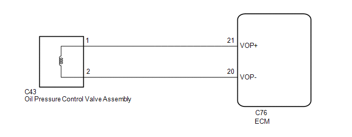
WIRING DIAGRAM
CAUTION / NOTICE / HINT
HINT:
Read Freeze Frame Data using the GTS. The ECM records vehicle and driving condition information as Freeze Frame Data the moment a DTC is stored. When troubleshooting, Freeze Frame Data can help determine if the vehicle was moving or stationary, if the engine was warmed up or not, if the air fuel ratio was lean or rich, and other data from the time the malfunction occurred.
PROCEDURE
| 1. |
INSPECT OIL PRESSURE CONTROL VALVE ASSEMBLY |
Click here
| NG | .gif) | REPLACE OIL PRESSURE CONTROL VALVE ASSEMBLY |
|
.gif)
| 2. |
CHECK HARNESS AND CONNECTOR (OIL PRESSURE CONTROL VALVE ASSEMBLY - ECM) |
(a) Disconnect the oil pressure control valve assembly connector.
(b) Disconnect the ECM connector.
(c) Measure the resistance according to the value(s) in the table below.
Standard Resistance:
|
Tester Connection | Condition |
Specified Condition |
|---|---|---|
|
C43-1 - C76-21 (VOP+) |
Always | Below 1 Ω |
|
C43-2 - C76-20 (VOP-) |
Always | Below 1 Ω |
|
C43-1 or C76-21 (VOP+) - Body ground and other terminals |
Always | 10 kΩ or higher |
|
C43-2 or C76-20 (VOP-) - Body ground and other terminals |
Always | 10 kΩ or higher |
| OK | | REPLACE ECM
|
| NG | | REPAIR OR REPLACE HARNESS OR CONNECTOR |


