Toyota Corolla Cross: Automatic High Beam Switch Indicator does not Come ON
DESCRIPTION
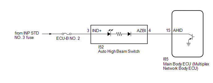
When the automatic high beam system is on, the main body ECU (multiplex network body ECU) illuminates the auto high beam switch indicator.
WIRING DIAGRAM
CAUTION / NOTICE / HINT
NOTICE:
- Inspect the fuses for circuits related to this system before performing the following procedure.
- Before replacing the main body ECU (multiplex network body ECU), refer
to Registration.*1
for HEV Model: Click here
.gif)
for Gasoline: Click here
- *1: w/ Smart Key System
PROCEDURE
|
1. |
PERFORM ACTIVE TEST USING GTS |
(a) Perform the Active Test according to the display on the GTS.
Body Electrical > Main Body > Data List|
Tester Display |
Measurement Item |
Range |
Normal Condition |
Diagnostic Note |
|---|---|---|---|---|
|
Auto High Beam Main Switch |
Auto high beam switch signal |
OFF or ON |
OFF: Auto high beam switch not pressed ON: Auto high beam switch pressed |
- |
|
Tester Display |
|---|
|
Automatic High Beam Switch Light |
OK:
Auto high beam switch indicator light illuminates.
| OK | .gif)
|
USE SIMULATION METHOD TO CHECK |
|
.gif)
|
2. |
INSPECT AUTO HIGH BEAM SWITCH |
HINT:
Click here
| NG |
|
REPLACE AUTO HIGH BEAM SWITCH |
|
|
3. |
CHECK HARNESS AND CONNECTOR (POWER SOURCE - AUTO HIGH BEAM SWITCH) |
(a) Measure the voltage according to the value(s) in the table below.
Standard Voltage:
|
Tester Connection |
Switch Condition |
Specified Condition |
|---|---|---|
|
I52-3 (IND+) - Body ground |
Always |
11 to 14 V |
| NG |
|
REPAIR OR REPLACE HARNESS OR CONNECTOR |
|
|
4. |
CHECK HARNESS AND CONNECTOR (AUTO HIGH BEAM SWITCH - MAIN BODY ECU (MULTIPLEX NETWORK BODY ECU)) |
(a) Disconnect the I85 main body ECU (multiplex network body ECU) connector.
(b) Measure the resistance according to the value(s) in the table below.
Standard Resistance:
|
Tester Connection |
Condition |
Specified Condition |
|---|---|---|
|
I52-4 (AZBI) - I85-15 (AHID) |
Always |
Below 1 Ω |
|
I52-4 (AZBI) or I85-15 (AHID) - Body ground |
Always |
10 kΩ or higher |
| OK |
|
REPLACE MAIN BODY ECU (MULTIPLEX NETWORK BODY ECU) |
| NG |
|
REPAIR OR REPLACE HARNESS OR CONNECTOR |


