Toyota Corolla Cross: Removal
REMOVAL
CAUTION / NOTICE / HINT
The necessary procedures (adjustment, calibration, initialization, or registration) that must be performed after parts are replaced during forward recognition camera removal/installation are shown below.
Necessary Procedure After Parts Removed/Installed/Replaced|
Replacement Part or Performed Procedure |
Necessary Procedure |
Effect/Inoperative Function when Necessary Procedure not Performed |
Link |
|---|---|---|---|
| *When only removing and installing the forward recognition camera, it is not necessary to perform forward recognition camera optical axis learning. | |||
|
Forward recognition camera |
Update ECU security key |
Vehicle Control History (RoB) are stored |
|
|
Software version confirmation |
|
|
|
|
Adjust forward recognition camera |
|
One Time Recognition:
Driving Adjustment:
Camera Axis Adjustment Value Write:
|
|
NOTICE:
- When replacing the forward recognition camera, replace it with a new one.
- Do not touch the camera lens or the front windshield glass in front of the camera.
- If the forward recognition camera has been struck or dropped, replace it with a new one.
- When replacing the windshield glass of a vehicle equipped with a forward recognition camera, make sure to use a Toyota genuine part. If a non-Toyota genuine part is used, the forward recognition camera may not be able to be installed due to a missing bracket. Also, the front camera system or automatic high beam system may not operate properly due to a difference in the transmissivity or black ceramic border.
CAUTION / NOTICE / HINT
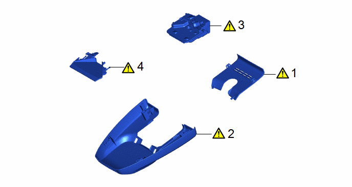
COMPONENTS (REMOVAL)
|
Procedure |
Part Name Code |
.png) |
.png) |
.png) |
|
|---|---|---|---|---|---|
|
1 |
NO. 2 FORWARD RECOGNITION COVER |
86466E |
|
- |
- |
|
2 |
NO. 1 FORWARD RECOGNITION COVER |
86466D |
|
- |
- |
|
3 |
FORWARD RECOGNITION CAMERA |
8646C |
|
- |
- |
|
4 |
FORWARD RECOGNITION HOOD |
- |
|
- |
- |
PROCEDURE
1. REMOVE NO. 2 FORWARD RECOGNITION COVER
.png) |
NOTICE: If these claws are disengaged separately, they may break. Insert a molding remover between them and pull it down to disengage the claws simultaneously. |

 |
Remove in this Direction (1) |
 |
Remove in this Direction (2) |
2. REMOVE NO. 1 FORWARD RECOGNITION COVER
.png) |
NOTICE: To avoid damaging the guides, always slide the No. 1 forward recognition cover parallel to the windshield glass. |

 |
Remove in this Direction |
- |
- |
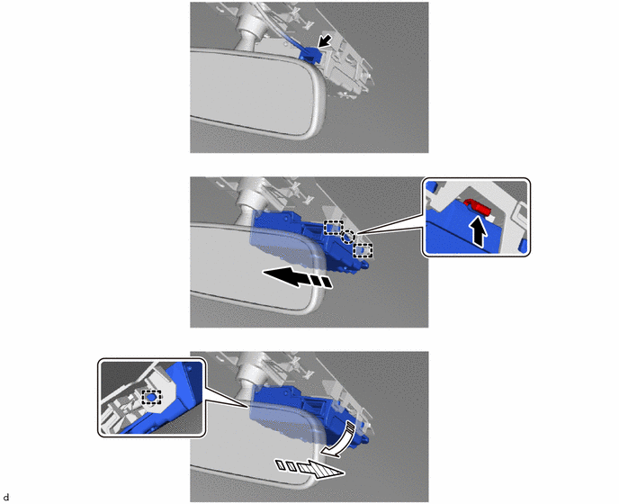
3. REMOVE FORWARD RECOGNITION CAMERA
.png) |
NOTICE:
|

 |
Push |
 |
Remove in this Direction (1) |
 |
Remove in this Direction (2) |
 |
Remove in this Direction (3) |
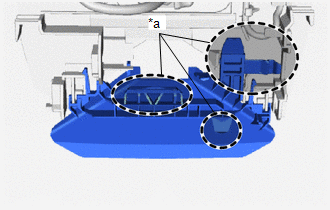
4. REMOVE FORWARD RECOGNITION HOOD
.png) |
NOTICE:
HINT: Perform this procedure only when replacement of the forward recognition hood is necessary. |

 |
Push |
 |
Remove in this Direction |

.gif)


