Toyota Corolla Cross: ABS Malfunction (C1296)
DESCRIPTION
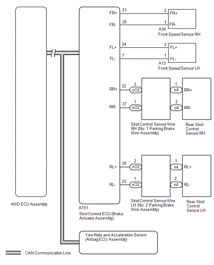
When a malfunction has occurred in the speed sensor circuit or the yaw rate and acceleration sensor circuit, the 4WD ECU assembly stores DTC C1296.
|
DTC No. |
Detection Item |
DTC Detection Condition |
Trouble Area |
|---|---|---|---|
|
C1296 |
ABS Malfunction |
|
|
WIRING DIAGRAM

PROCEDURE
|
1. |
CHECK FOR DTC (ELECTRONICALLY CONTROLLED BRAKE SYSTEM) |
(a) Clear the DTC.
Chassis > Brake/EPB > Clear DTCs(b) Turn the ignition switch off.
(c) Drive the vehicle, accelerate to a speed of 20 km/h (12 mph) or more, and check if the speed sensor DTC (electronically controlled brake system DTC) is output.
Chassis > Brake/EPB > Trouble Codes|
Result |
Proceed to |
|---|---|
|
Electronically controlled brake system DTC (speed sensor or acceleration sensor DTC) is not output |
A |
|
Electronically controlled brake system DTC (speed sensor or acceleration sensor DTC) is output |
B |
HINT:
When DTCs indicating a CAN communication system malfunction are output, repair the CAN communication system before repairing each corresponding sensor.
| B | .gif) |
GO TO ELECTRONICALLY CONTROLLED BRAKE SYSTEM |
|
|
2. |
READ VALUE USING GTS (WHEEL SPEED) |
(a) Read the value displayed on the GTS.
Chassis > Four Wheel Drive > Data List|
Tester Display |
Measurement Item |
Range |
Normal Condition |
Diagnostic Note |
|---|---|---|---|---|
|
FR Wheel Speed |
Front wheel speed sensor RH reading |
Min.: 0 km/h (0 mph) Max.: 326 km/h (203 mph) |
Vehicle stopped: 0 km/h (0 mph) |
No large fluctuations when driving at a constant speed. |
|
FL Wheel Speed |
Front wheel speed sensor LH reading |
Min.: 0 km/h (0 mph) Max.: 326 km/h (203 mph) |
Vehicle stopped: 0 km/h (0 mph) |
No large fluctuations when driving at a constant speed. |
|
RR Wheel Speed |
Rear wheel speed sensor RH reading |
Min.: 0 km/h (0 mph) Max.: 326 km/h (203 mph) |
Vehicle stopped: 0 km/h (0 mph) |
No large fluctuations when driving at a constant speed. |
|
RL Wheel Speed |
Rear wheel speed sensor LH reading |
Min.: 0 km/h (0 mph) Max.: 326 km/h (203 mph) |
Vehicle stopped: 0 km/h (0 mph) |
No large fluctuations when driving at a constant speed. |
|
Tester Display |
|---|
|
FR Wheel Speed |
|
FL Wheel Speed |
|
RR Wheel Speed |
|
RL Wheel Speed |
OK:
The speed value output from the speed sensor displayed on the GTS is the same as the actual vehicle speed measured using a speedometer tester (calibrated chassis dynamometer).
| NG | .gif) |
GO TO ELECTRONICALLY CONTROLLED BRAKE SYSTEM |
|
|
3. |
READ VALUE USING GTS (FORWARD AND REARWARD G) |
(a) Read the value displayed on the GTS.
Chassis > Four Wheel Drive|
Tester Display |
Measurement Item |
Range |
Normal Condition |
Diagnostic Note |
|---|---|---|---|---|
|
Forward and Rearward G |
Forward and Rearward G |
Min.: -25.10 m/s2 Max.: 24.90 m/s2 |
Approximately 0 +/-0.13 m/s2 while stationary |
Changes in proportion with acceleration during acceleration/deceleration. |
|
Tester Display |
|---|
|
Forward and Rearward G |
OK:
The yaw rate and acceleration sensor (airbag ECU assembly) output value is normal.
| OK | .gif) |
REPLACE 4WD ECU ASSEMBLY |
| NG | .gif) |
GO TO ELECTRONICALLY CONTROLLED BRAKE SYSTEM |

.gif)

