Toyota Corolla Cross: Speaker Circuit
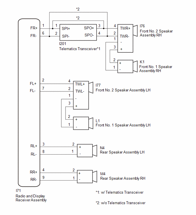
WIRING DIAGRAM
CAUTION / NOTICE / HINT
NOTICE:
- When replacing the telematics transceiver, make sure to replace it with a new one.
- Depending on the parts that are replaced during vehicle inspection or
maintenance, performing initialization, registration or calibration may
be needed.
Click here
.gif)
PROCEDURE
|
1. |
CHECK MODEL |
|
Result |
Proceed to |
|---|---|
|
w/ Telematics Transceiver |
A |
|
w/o Telematics Transceiver |
B |
| B | .gif)
|
GO TO STEP 12 |
|
.gif)
|
2. |
CHECK SPEAKER (OPERATION CHECK) |
|
(a) Enter diagnostic mode. Click here |
|
(b) Select "Failure Diagnosis" from the "Service Menu" screen.
(c) Select "System Check" from the "Failure Diagnosis" screen.
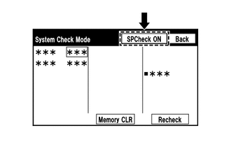
(d) Select "SPCheck ON" from the "System Check Mode" screen and perform speaker check.
OK:
Each speaker outputs sound from the selected audio source properly.
|
Result |
Proceed to |
|---|---|
|
Front No. 1 speaker assembly or front No. 2 speaker assembly does not outputs sound |
A |
|
Rear speaker assembly does not outputs sound |
B |
| B |
|
GO TO STEP 10 |
|
|
3. |
CHECK HARNESS AND CONNECTOR (RADIO AND DISPLAY RECEIVER ASSEMBLY - FRONT NO. 2 SPEAKER ASSEMBLY LH, TELEMATICS TRANSCEIVER) |
(a) Disconnect the I71 radio and display receiver assembly connector.
(b) Disconnect the I77 front No. 2 speaker assembly LH connector.
(c) Disconnect the I201 telematics transceiver connector.
(d) Measure the resistance according to the value(s) in the table below.
Standard Resistance:
|
Tester Connection |
Condition |
Specified Condition |
|---|---|---|
|
I71-1 (FR+) - I201-1 (SPI+) |
Always |
Below 1 Ω |
|
I71-2 (FL+) - I77-4 (TWL+) |
Always |
Below 1 Ω |
|
I71-6 (FR-) - I201-2 (SPI-) |
Always |
Below 1 Ω |
|
I71-7 (FL-) - I77-2 (TWL-) |
Always |
Below 1 Ω |
|
I71-1 (FR+) or I201-1 (SPI+) - Body ground |
Always |
10 kΩ or higher |
|
I71-2 (FL+) or I77-4 (TWL+) - Body ground |
Always |
10 kΩ or higher |
|
I71-6 (FR-) or I201-2 (SPI-) - Body ground |
Always |
10 kΩ or higher |
|
I71-7 (FL-) or I77-2 (TWL-) - Body ground |
Always |
10 kΩ or higher |
| NG |
|
REPAIR OR REPLACE HARNESS AND CONNECTOR |
|
|
4. |
CHECK HARNESS AND CONNECTOR (FRONT NO. 1 SPEAKER ASSEMBLY LH - FRONT NO. 2 SPEAKER ASSEMBLY LH) |
(a) Disconnect the L1 front No. 1 speaker assembly LH connector.
(b) Disconnect the I77 front No. 2 speaker assembly LH connector.
(c) Measure the resistance according to the value(s) in the table below.
Standard Resistance:
|
Tester Connection |
Condition |
Specified Condition |
|---|---|---|
|
L1-2 (+) - I77-3 (+) |
Always |
Below 1 Ω |
|
L1-1 (-) - I77-1 (-) |
Always |
Below 1 Ω |
|
L1-2 (+) or I77-3 (+) - Body ground |
Always |
10 kΩ or higher |
|
L1-1 (-) or I77-1 (-) - Body ground |
Always |
10 kΩ or higher |
| NG |
|
REPAIR OR REPLACE HARNESS OR CONNECTOR |
|
|
5. |
CHECK HARNESS AND CONNECTOR (FRONT NO. 2 SPEAKER ASSEMBLY RH - TELEMATICS TRANSCEIVER) |
(a) Disconnect the I76 front No. 2 speaker assembly RH connector.
(b) Disconnect the I201 telematics transceiver connector.
(c) Measure the resistance according to the value(s) in the table below.
Standard Resistance:
|
Tester Connection |
Condition |
Specified Condition |
|---|---|---|
|
I76-4 (+) - I201-3 (SPO+) |
Always |
Below 1 Ω |
|
I76-2 (-) - I201-4 (SPO-) |
Always |
Below 1 Ω |
|
I76-4 (+) or I201-3 (SPO+) - Body ground |
Always |
10 kΩ or higher |
|
I76-2 (-) or I201-4 (SPO-) - Body ground |
Always |
10 kΩ or higher |
| NG |
|
REPAIR OR REPLACE HARNESS OR CONNECTOR |
|
|
6. |
CHECK HARNESS AND CONNECTOR (FRONT NO. 1 SPEAKER ASSEMBLY RH - FRONT NO. 2 SPEAKER ASSEMBLY RH) |
(a) Disconnect the K1 front No. 1 speaker assembly RH connector.
(b) Disconnect the I76 front No. 2 speaker assembly RH connector.
(c) Measure the resistance according to the value(s) in the table below.
Standard Resistance:
|
Tester Connection |
Condition |
Specified Condition |
|---|---|---|
|
K1-2 (+) - I76-3 (+) |
Always |
Below 1 Ω |
|
K1-1 (-) - I76-1 (-) |
Always |
Below 1 Ω |
|
K1-2 (+) or I76-3 (+) - Body ground |
Always |
10 kΩ or higher |
|
K1-1 (-) or I76-1 (-) - Body ground |
Always |
10 kΩ or higher |
| NG |
|
REPAIR OR REPLACE HARNESS OR CONNECTOR |
|
|
7. |
INSPECT FRONT NO. 1 SPEAKER ASSEMBLY |
Click here
| NG |
|
REPLACE FRONT NO. 1 SPEAKER ASSEMBLY |
|
|
8. |
INSPECT FRONT NO. 2 SPEAKER ASSEMBLY |
Click here
| NG |
|
REPLACE FRONT NO. 2 SPEAKER ASSEMBLY |
|
|
9. |
INSPECT TELEMATICS TRANSCEIVER |
|
(a) Remove the telematics transceiver. Click here |
|
.png)
(b) Measure the resistance according to the value(s) in the table below.
Standard Resistance:
|
Tester Connection |
Condition |
Specified Condition |
|---|---|---|
|
1 (SPI+) - 3 (SPO+) |
Always |
Below 1 Ω |
|
2 (SPI-) - 4 (SPO-) |
Always |
Below 1 Ω |
|
1 (SPI+) - 2 (SPI-) |
Always |
10 kΩ or higher |
|
3 (SPO+) - 4 (SPO-) |
Always |
10 kΩ or higher |
| OK |
|
REPLACE RADIO AND DISPLAY RECEIVER ASSEMBLY |
| NG |
|
REPLACE TELEMATICS TRANSCEIVER |
|
10. |
CHECK HARNESS AND CONNECTOR (RADIO AND DISPLAY RECEIVER ASSEMBLY - REAR SPEAKER ASSEMBLY) |
(a) Disconnect the I71 radio and display receiver assembly connector.
(b) Disconnect the M4 rear speaker assembly RH connector.
(c) Disconnect the N4 rear speaker assembly LH connector.
(d) Measure the resistance according to the value(s) in the table below.
Standard Resistance:
|
Tester Connection |
Condition |
Specified Condition |
|---|---|---|
|
I71-4 (RR+) - M4-2 (+) |
Always |
Below 1 Ω |
|
I71-3 (RL+) - N4-2 (+) |
Always |
Below 1 Ω |
|
I71-9 (RR-) - M4-1 (-) |
Always |
Below 1 Ω |
|
I71-8 (RL-) - N4-1 (-) |
Always |
Below 1 Ω |
|
I71-4 (RR+) or M4-2 (+) - Body ground |
Always |
10 kΩ or higher |
|
I71-3 (RL+) or N4-2 (+) - Body ground |
Always |
10 kΩ or higher |
|
I71-9 (RR-) or M4-1 (-) - Body ground |
Always |
10 kΩ or higher |
|
I71-8 (RL-) or N4-1 (-) - Body ground |
Always |
10 kΩ or higher |
| NG |
|
REPAIR OR REPLACE HARNESS OR CONNECTOR |
|
|
11. |
INSPECT REAR SPEAKER ASSEMBLY |
Click here
| OK |
|
REPLACE RADIO AND DISPLAY RECEIVER ASSEMBLY |
| NG |
|
REPLACE REAR SPEAKER ASSEMBLY |
|
12. |
CHECK SPEAKER (OPERATION CHECK) |
|
(a) Enter diagnostic mode. Click here |
|
(b) Select "Failure Diagnosis" from the "Service Menu" screen.
(c) Select "System Check" from the "Failure Diagnosis" screen.
(d) Select "SPCheck ON" from the "System Check Mode" screen and perform speaker check.
OK:
Each speaker outputs sound from the selected audio source properly.
|
Result |
Proceed to |
|---|---|
|
Front No. 1 speaker assembly or front No. 2 speaker assembly does not outputs sound |
A |
|
Rear speaker assembly does not outputs sound |
B |
| B |
|
GO TO STEP 18 |
|
|
13. |
CHECK HARNESS AND CONNECTOR (RADIO AND DISPLAY RECEIVER ASSEMBLY - FRONT NO. 2 SPEAKER ASSEMBLY LH, TELEMATICS TRANSCEIVER) |
(a) Disconnect the I71 radio and display receiver assembly connector.
(b) Disconnect the I76 front No. 2 speaker assembly RH connector.
(c) Disconnect the I77 front No. 2 speaker assembly LH connector.
(d) Measure the resistance according to the value(s) in the table below.
Standard Resistance:
|
Tester Connection |
Condition |
Specified Condition |
|---|---|---|
|
I71-1 (FR+) - I76-4 (TWR+) |
Always |
Below 1 Ω |
|
I71-2 (FL+) - I77-4 (TWL+) |
Always |
Below 1 Ω |
|
I71-6 (FR-) - I76-2 (TWR-) |
Always |
Below 1 Ω |
|
I71-7 (FL-) - I77-2 (TWL-) |
Always |
Below 1 Ω |
|
I71-1 (FR+) or I76-4 (TWR+) - Body ground |
Always |
10 kΩ or higher |
|
I71-2 (FL+) or I77-4 (TWL+) - Body ground |
Always |
10 kΩ or higher |
|
I71-6 (FR-) or I77-2 (TWR-) - Body ground |
Always |
10 kΩ or higher |
|
I71-7 (FL-) or I77-2 (TWL-) - Body ground |
Always |
10 kΩ or higher |
| NG |
|
REPAIR OR REPLACE HARNESS AND CONNECTOR |
|
|
14. |
CHECK HARNESS AND CONNECTOR (FRONT NO. 1 SPEAKER ASSEMBLY RH - FRONT NO. 2 SPEAKER ASSEMBLY RH) |
(a) Disconnect the K1 front No. 1 speaker assembly RH connector.
(b) Disconnect the I76 front No. 2 speaker assembly RH connector.
(c) Measure the resistance according to the value(s) in the table below.
Standard Resistance:
|
Tester Connection |
Condition |
Specified Condition |
|---|---|---|
|
K1-2 (+) - I76-3 (+) |
Always |
Below 1 Ω |
|
K1-1 (-) - I76-1 (-) |
Always |
Below 1 Ω |
|
K1-2 (+) or I76-3 (+) - Body ground |
Always |
10 kΩ or higher |
|
K1-1 (-) or I76-1 (-) - Body ground |
Always |
10 kΩ or higher |
| NG |
|
REPAIR OR REPLACE HARNESS OR CONNECTOR |
|
|
15. |
CHECK HARNESS AND CONNECTOR (FRONT NO. 1 SPEAKER ASSEMBLY LH - FRONT NO. 2 SPEAKER ASSEMBLY LH) |
(a) Disconnect the L1 front No. 1 speaker assembly LH connector.
(b) Disconnect the I77 front No. 2 speaker assembly LH connector.
(c) Measure the resistance according to the value(s) in the table below.
Standard Resistance:
|
Tester Connection |
Condition |
Specified Condition |
|---|---|---|
|
L1-2 (+) - I77-3 (+) |
Always |
Below 1 Ω |
|
L1-1 (-) - I77-1 (-) |
Always |
Below 1 Ω |
|
L1-2 (+) or I77-3 (+) - Body ground |
Always |
10 kΩ or higher |
|
L1-1 (-) or I77-1 (-) - Body ground |
Always |
10 kΩ or higher |
| NG |
|
REPAIR OR REPLACE HARNESS OR CONNECTOR |
|
|
16. |
INSPECT FRONT NO. 1 SPEAKER ASSEMBLY |
Click here
| NG |
|
REPLACE FRONT NO. 1 SPEAKER ASSEMBLY |
|
|
17. |
INSPECT FRONT NO. 2 SPEAKER ASSEMBLY |
Click here
| OK |
|
REPLACE RADIO AND DISPLAY RECEIVER ASSEMBLY |
| NG |
|
REPLACE FRONT NO. 2 SPEAKER ASSEMBLY |
|
18. |
CHECK HARNESS AND CONNECTOR (RADIO AND DISPLAY RECEIVER ASSEMBLY - REAR SPEAKER ASSEMBLY) |
(a) Disconnect the I71 radio and display receiver assembly connector.
(b) Disconnect the M4 rear speaker assembly RH connector.
(c) Disconnect the N4 rear speaker assembly LH connector.
(d) Measure the resistance according to the value(s) in the table below.
Standard Resistance:
|
Tester Connection |
Condition |
Specified Condition |
|---|---|---|
|
I71-4 (RR+) - M4-2 (+) |
Always |
Below 1 Ω |
|
I71-3 (RL+) - N4-2 (+) |
Always |
Below 1 Ω |
|
I71-9 (RR-) - M4-1 (-) |
Always |
Below 1 Ω |
|
I71-8 (RL-) - N4-1 (-) |
Always |
Below 1 Ω |
|
I71-4 (RR+) or M4-2 (+) - Body ground |
Always |
10 kΩ or higher |
|
I71-3 (RL+) or N4-2 (+) - Body ground |
Always |
10 kΩ or higher |
|
I71-9 (RR-) or M4-1 (-) - Body ground |
Always |
10 kΩ or higher |
|
I71-8 (RL-) or N4-1 (-) - Body ground |
Always |
10 kΩ or higher |
| NG |
|
REPAIR OR REPLACE HARNESS OR CONNECTOR |
|
|
19. |
INSPECT REAR SPEAKER ASSEMBLY |
Click here
| OK |
|
REPLACE RADIO AND DISPLAY RECEIVER ASSEMBLY |
| NG |
|
REPLACE REAR SPEAKER ASSEMBLY |


