Toyota Corolla Cross: Steering Angle Sensor (C1297)
DESCRIPTION
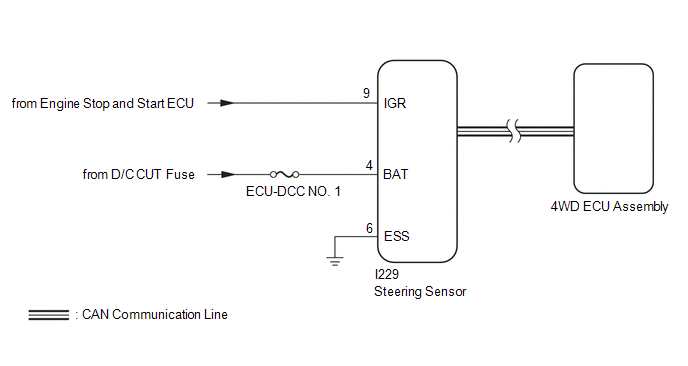
The 4WD ECU assembly receives signals from the steering sensor, and thereby detects the steering angle of the steering wheel assembly to determine when the vehicle is turning.
When an abnormal signal is received from the steering sensor, the 4WD ECU assembly stores DTC C1297.
|
DTC No. |
Detection Item |
DTC Detection Condition |
Trouble Area |
|---|---|---|---|
|
C1297 |
Steering Angle Sensor |
When the ignition switch is ON (IG1 terminal voltage is 9.5 V or more), an abnormal signal is received from the steering sensor. |
|
WIRING DIAGRAM
CAUTION / NOTICE / HINT
NOTICE:
Inspect the fuses for circuits related to this system before performing the following inspection procedure.
PROCEDURE
|
1. |
CHECK FOR DTC |
(a) Clear the DTC.
Chassis > Four Wheel Drive > Clear DTCs(b) Turn the ignition switch off.
(c) Turn the ignition switch to ON again and check that no CAN communication system DTC(s) is output.
Click here .gif)
(d) Start the engine.
(e) Drive the vehicle at a speed of 35 km/h (22 mph), turn the steering wheel to the right and left and check that no electronically controlled brake system (steering sensor) DTC is output.
Chassis > Brake/EPB > Trouble Codes|
Result |
Proceed to |
|---|---|
|
Neither CAN communication system DTC nor electronically controlled brake system DTC is output |
A |
|
CAN communication system DTC is output |
B |
|
Electronically controlled brake system (steering sensor) DTC is output |
C |
HINT:
When DTCs indicating a CAN communication system malfunction are output, repair the CAN communication system before repairing each corresponding sensor.
| B | .gif) |
GO TO CAN COMMUNICATION SYSTEM |
| C | |
GO TO ELECTRONICALLY CONTROLLED BRAKE SYSTEM |
|
.gif)
|
2. |
CHECK HARNESS AND CONNECTOR (POWER SOURCE TERMINAL) |
|
(a) Disconnect the steering sensor connector. |
|
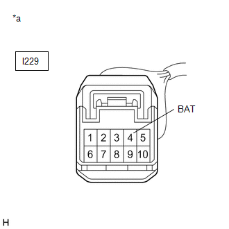
(b) Measure the voltage according to the value(s) in the table below.
Standard Voltage:
|
Tester Connection |
Condition |
Specified Condition |
|---|---|---|
|
I229-4 (BAT) - Body ground |
Always |
11 to 14 V |
| NG | |
REPAIR OR REPLACE HARNESS OR CONNECTOR |
|
|
3. |
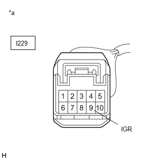
CHECK TERMINAL VOLTAGE (IG TERMINAL) |
(a) Turn the ignition switch to ON.
|
(b) Measure the voltage according to the value(s) in the table below. Standard Voltage:
|
|
| NG | |
INSPECT STOP AND START SYSTEM |
|
|
4. |
CHECK HARNESS AND CONNECTOR (ESS TERMINAL) |
(a) Turn the ignition switch off.
(b) Measure the resistance according to the value(s) in the table below.
Standard Resistance:
|
Tester Connection |
Condition |
Specified Condition |
|---|---|---|
|
I229-6 (ESS) - Body ground |
Always |
Below 1 Ω |
| NG | |
REPAIR OR REPLACE HARNESS OR CONNECTOR |
|
|
5. |
READ VALUE USING GTS (STEERING ANGLE VALUE) |
(a) Read the value displayed on the GTS.
Chassis > Four Wheel Drive > Data List|
Tester Display |
Measurement Item |
Range |
Normal Condition |
Diagnostic Note |
|---|---|---|---|---|
|
Steering Angle Value |
Steering angle value |
Min.: -3276.8° Max.: 3276.7° |
Left turn: Increase Right turn: Decrease |
Changes in proportion with the amount of steering wheel rotation during steering operation. |
|
Tester Display |
|---|
|
Steering Angle Value |
OK:
The steering sensor value changes in accordance with the steering wheel movement.
| OK | |
REPLACE 4WD ECU ASSEMBLY |
| NG | |
REPLACE STEERING SENSOR |

