Toyota Corolla Cross: System Diagram
SYSTEM DIAGRAM
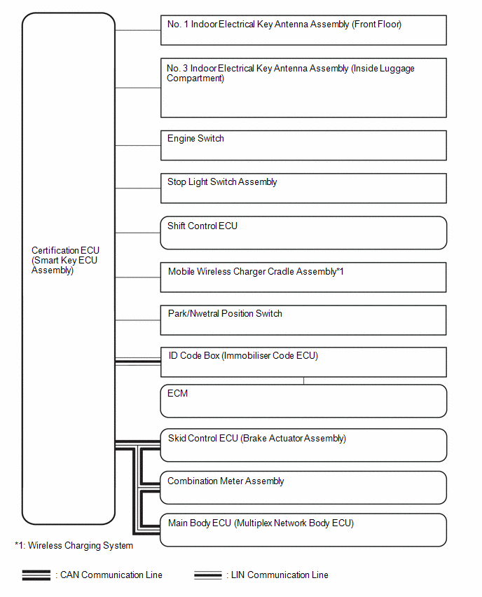
SMART KEY SYSTEM (for Start Function)
SMART KEY SYSTEM (for Entry Function)
Click here .gif)
READ NEXT:
CAUTION / NOTICE / HINT
NOTICE:
Do not perform "Smart Code Reset" (all key ID erasure) until all malfunctions and symptoms have been confirmed and resolved. If all key ID erasure is performed wi
CUSTOMER PROBLEM ANALYSIS CHECK
HINT: Be sure to ask the customer in detail about the following points concerning the vehicle operating conditions, environment and problem, and then check for DT
CHECK FOR INTERMITTENT PROBLEMS
NOTICE:
Operation history is stored in the RAM or EEPROM of the certification ECU (smart key ECU assembly). As the cause of a malfunction stored in the RAM will b
SEE MORE:
CUSTOMIZE PARAMETERS CUSTOMIZE THEFT DETERRENT SYSTEM
NOTICE:
When the customer requests a change in a function, first make sure that the function can be customized.
Be sure to make a note of the current settings before customizing.
When troubleshooting a function, first make sure tha
INSTALLATION CAUTION / NOTICE / HINT COMPONENTS (INSTALLATION)
Procedure Part Name Code
1 AIR CONDITIONING AMPLIFIER ASSEMBLY
88650N -
- -
2 ACCELERATOR PEDAL SENSOR ASSEMBLY
78110K -
- -
3 CONNECT CABLE TO NE
 How To Proceed With Troubleshooting
 Customize Parameters
