Toyota Corolla Cross: Diameter of the Tire is not Uniform (C1337)
DESCRIPTION
The 4WD ECU assembly outputs DTC C1337 if a difference in tire size is detected.
|
DTC No. |
Detection Item |
DTC Detection Condition |
Trouble Area |
|---|---|---|---|
|
C1337 |
Diameter of the Tire is not Uniform |
When the following continues for 36 seconds or more:
|
|
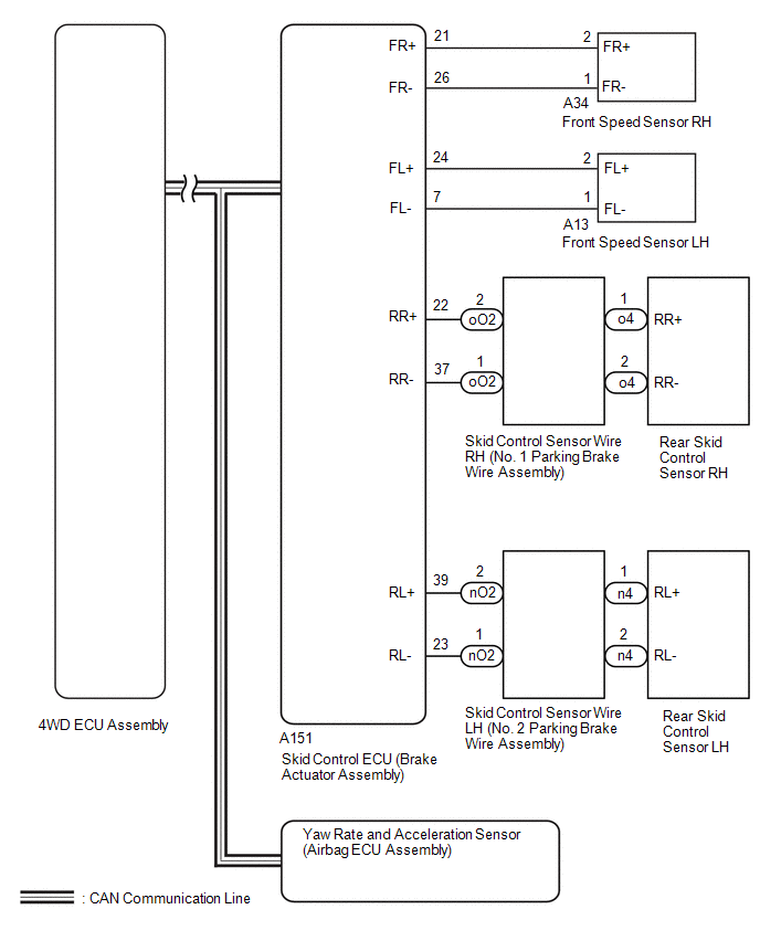
WIRING DIAGRAM
PROCEDURE
|
1. |
CHECK TIRE CONDITION |
(a) Check the size and condition of all 4 tires.
HINT:
This DTC is output when tire deformation or a difference in tire size is detected.
OK:
The diameter and air pressure of all 4 tires are the same.
| NG | .gif) |
REPLACE PERFORM AIR PRESSURE ADJUSTMENT OR REPLACE TIRES SO THAT ALL 4 TIRES ARE SAME IN SIZE |
|
.gif)
|
2. |
CHECK FOR DTC |
(a) Clear the DTCs.
Chassis > Four Wheel Drive > Clear DTCs(b) Start the engine.
(c) Drive the vehicle at a speed of 30 km/h (19 mph) or more for 36 seconds or more so that the same DTC is output.
Chassis > Four Wheel Drive > Trouble Codes(d) Check if the speed sensor DTC (electronically controlled brake system DTC) is output.
Chassis > Brake/EPB > Trouble Codes(e) Read the DTCs using the GTS.
|
Result |
Proceed to |
|---|---|
|
Only "C1377" is output |
A |
|
Speed sensor DTC (electronically controlled brake system DTC) is output |
B |
|
DTC is not output |
C |
| B | |
GO TO ELECTRONICALLY CONTROLLED BRAKE SYSTEM |
| C | |
CHECK FOR INTERMITTENT PROBLEMS |
|
|
3. |
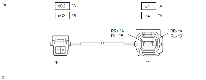
INSPECT PARKING BRAKE WIRE ASSEMBLY |
|
*A |
RH |
*B |
LH |
|
*a |
Front view of Parking Brake Wire Assembly |
*b |
(to Wire Harness Connector) |
|
*c |
(to Parking Brake Actuator Assembly) |
- |
- |
(a) Remove the parking brake wire assembly.
(b) Check the parking brake wire assembly for damage.
OK:
No damage.
HINT:
If damaged, there may be a short in the wire harness or a short to ground.
(c) Inspect the parking brake wire assembly.
Standard Resistance:
RH|
Tester Connection |
Condition |
Specified Condition |
|---|---|---|
|
oO2-1 - o4-2 (RR-) |
Always |
Below 1 Ω |
|
oO2-2 - o4-1 (RR+) |
Always |
10 kΩ or higher |
|
oO2-1 or o4-2 (RR-) - Body ground |
Always |
10 kΩ or higher |
|
oO2-2 - o4-1 (RR+) |
Always |
Below 1 Ω |
|
oO2-1 - o4-2 (RR-) |
Always |
10 kΩ or higher |
|
oO2-2 or o4-1 (RR+) - Body ground |
Always |
10 kΩ or higher |
|
Tester Connection |
Condition |
Specified Condition |
|---|---|---|
|
nO2-1 - n4-2 (RL-) |
Always |
Below 1 Ω |
|
nO2-2 - n4-1 (RL+) |
Always |
10 kΩ or higher |
|
nO2-1 or n4-2 (RL-) - Body ground |
Always |
10 kΩ or higher |
|
nO2-2 - n4-1 (RL+) |
Always |
Below 1 Ω |
|
nO2-1 - n4-2 (RL-) |
Always |
10 kΩ or higher |
|
nO2-2 or n4-1 (RL+) - Body ground |
Always |
10 kΩ or higher |
| NG | |
REPLACE PARKING BRAKE WIRE ASSEMBLY |
|
|
4. |
CHECK HARNESS AND CONNECTOR (SPEED SENSOR - SKID CONTROL ECU (BRAKE ACTUATOR ASSEMBLY)) |
(a) Make sure that there is no looseness at the locking part and the connecting part of the connectors.
(b) Turn the ignition switch off.
(c) Disconnect the A151 skid control ECU (brake actuator assembly) connector.
(d) Disconnect the A13, A34, o4 and/or n4 speed sensor connector(s).
(e) Measure the resistance according to the value(s) in the table below.
Standard Resistance:
for Front RH:|
Tester Connection |
Condition |
Specified Condition |
|---|---|---|
|
A151-21 (FR+) - A34-2 (FR+) |
Always |
Below 1 Ω |
|
A151-21 (FR+) or A34-2 (FR+) - Body ground |
Always |
10 kΩ or higher |
|
A151-26 (FR-) - A34-1 (FR-) |
Always |
Below 1 Ω |
|
A151-26 (FR-) or A34-1 (FR-) - Body ground |
Always |
10 kΩ or higher |
|
Tester Connection |
Condition |
Specified Condition |
|---|---|---|
|
A151-24 (FL+) - A13-2 (FL+) |
Always |
Below 1 Ω |
|
A151-24 (FL+) or A13-2 (FL+) - Body ground |
Always |
10 kΩ or higher |
|
A151-7 (FL-) - A13-1 (FL-) |
Always |
Below 1 Ω |
|
A151-7 (FL-) or A13-1 (FL-) - Body ground |
Always |
10 kΩ or higher |
|
Tester Connection |
Condition |
Specified Condition |
|---|---|---|
|
A151-22 (RR+) - o4-1 (RR+) |
Always |
Below 1 Ω |
|
A151-22 (RR+) or o4-1 (RR+) - Body ground |
Always |
10 kΩ or higher |
|
A151-37 (RR-) - o4-2 (RR-) |
Always |
Below 1 Ω |
|
A151-37 (RR-) or o4-2 (RR-) - Body ground |
Always |
10 kΩ or higher |
|
Tester Connection |
Condition |
Specified Condition |
|---|---|---|
|
A151-39 (RL+) - n4-1 (RL+) |
Always |
Below 1 Ω |
|
A151-39 (RL+) or n4-1 (RL+) - Body ground |
Always |
10 kΩ or higher |
|
A151-23 (RL-) - n4-2 (RL-) |
Always |
Below 1 Ω |
|
A151-23 (RL-) or n4-2 (RL-) - Body ground |
Always |
10 kΩ or higher |
| NG | |
REPAIR OR REPLACE HARNESS OR CONNECTOR |
|
|
5. |
PERFORM DEALER MODE (SIGNAL CHECK) |
(a) Turn the ignition switch off.
(b) Perform the sensor check in the Dealer Mode (Signal Check) procedure.
Click here .gif)
|
Tester Display |
|---|
|
Signal Check |
OK:
All Dealer Mode (Signal Check) DTCs are cleared.
| NG | |
GO TO STEP 7 |
|
|
6. |
RECONFIRM DTC |
(a) Clear the DTCs.
Chassis > Four Wheel Drive > Clear DTCs(b) Start the engine.
(c) Drive the vehicle at a speed of 30 km/h (19 mph) or more for 36 seconds or more so that the same DTC is output.
Chassis > Four Wheel Drive > Trouble Codes|
Result |
Proceed to |
|---|---|
|
DTC is output |
A |
|
DTC is not output |
B |
| A | |
REPLACE BRAKE ACTUATOR ASSEMBLY |
| B | |
CHECK FOR INTERMITTENT PROBLEMS |
|
7. |
CHECK SPEED SENSOR ROTOR |
(a) Turn the ignition switch off.
(b) Remove the front speed sensor rotor (front axle hub sub-assembly) or rear speed sensor rotor (rear axle hub and bearing assembly).
for Front Side: Click here
for Rear Side: Click here
(c) Check the speed sensor rotor.
OK:
No scratches, oil, or foreign matter on the rotors.
NOTICE:
Check the speed sensor signal after cleaning or replacement.
Click here
HINT:
- If the front speed sensor rotor needs to be replaced, replace it together with the front axle hub sub-assembly.
- If the rear speed sensor rotor needs to be replaced, replace it together with the rear axle hub and bearing assembly.
| NG | |
CLEAN OR REPLACE SPEED SENSOR ROTOR |
|
|
8. |
REPLACE SPEED SENSOR |
(a) Turn the ignition switch off.
(b) Replace the front speed sensor or the rear skid control sensor.
for Front Side: Click here
for Rear Side: Click here
NOTICE:
Check the speed sensor signal after replacement.
Click here
|
|
9. |
RECONFIRM DTC |
(a) Clear the DTC.
Chassis > Four Wheel Drive > Clear DTCs(b) Start the engine.
(c) Drive the vehicle at a speed of 30 km/h (19 mph) or more for 36 seconds or more so that the same DTC is output.
Chassis > Four Wheel Drive > Trouble Codes|
Result |
Proceed to |
|---|---|
|
DTC is output |
A |
|
DTC is not output |
B |
HINT:
Reinstall the sensor, connectors, etc. and restore the vehicle to its prior condition before rechecking DTCs.
| B | |
END |
|
|
10. |
REPLACE BRAKE ACTUATOR ASSEMBLY |
Click here
|
|
11. |
RECONFIRM DTC |
(a) Clear the DTC.
Chassis > Four Wheel Drive > Clear DTCs(b) Start the engine.
(c) Drive the vehicle at a speed of 30 km/h (19 mph) or more for 36 seconds or more so that the same DTC is output.
Chassis > Four Wheel Drive > Trouble Codes|
Result |
Proceed to |
|---|---|
|
DTC is output |
A |
|
DTC is not output |
B |
| A | |
REPLACE 4WD ECU ASSEMBLY |
| B | |
END |


