Toyota Corolla Cross: Starter Inrush Current Reduction Relay Circuit
DESCRIPTION
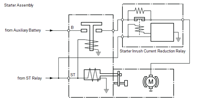
The starter inrush current reduction relay prevents the auxiliary battery voltage from becoming dropping excessively while the starter assembly is operating. If the auxiliary battery voltage drops below the threshold, stop and start control will be prohibited. In order to prevent this, the engine stop and start ECU operates the starter inrush current reduction relay for approximately 0.1 seconds after the ST relay is activated. By allowing current to flow to the starter inrush current reduction relay, the current that flows to the starter motor is reduced, preventing the auxiliary battery voltage from dropping excessively.
CAUTION / NOTICE / HINT
HINT:
- Starter inrush current reduction relay stuck on:
When the engine is started by stop and start control, a large amount of current will flow to the starter assembly, the auxiliary battery voltage will drop excessively and stop and start control will be canceled.
- Starter inrush current reduction relay stuck off:
Operating current will always flow through the starter inrush current reduction relay and the cranking speed will be low.
- For wire harness and connector inspection procedures and precautions, refer to "
.gif) "
"
PROCEDURE
|
1. | CHECK WAVEFORM (STARTER INRUSH CURRENT REDUCTION RELAY) |
(a) Connect the positive (+) lead of an oscilloscope to the positive (+) auxiliary battery terminal and the negative (-) lead to the negative (-) auxiliary battery terminal.
(b) While cranking the engine, count the number of times the waveform drops.
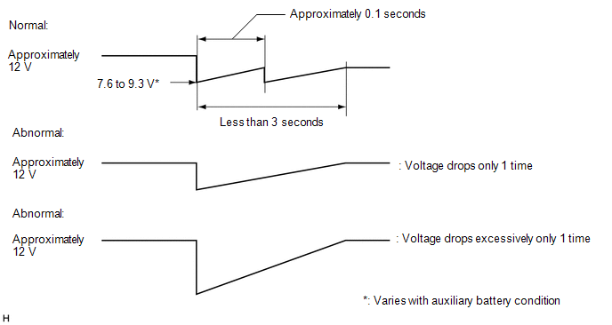
Standard:
Waveform drops 2 times
| OK | .gif) | PROCEED TO NEXT SUSPECTED AREA SHOWN IN PROBLEM SYMPTOMS TABLE |
| NG | | REPLACE STARTER INRUSH CURRENT REDUCTION RELAY |


