Toyota Corolla Cross: Failure to Restart from IG-ON Engine Stall
DESCRIPTION
This is the troubleshooting procedure for situations where the engine does not restart when attempting to restart it after a failed engine start occurred under stop and start system control.
CAUTION / NOTICE / HINT
PRECAUTIONS WHEN THE ENGINE STOP AND START ECU AND THE STARTER ASSEMBLY ARE REPLACED
NOTICE:
- When the engine stop and start ECU is replaced, it is necessary to read the number of starter operations before replacement and store this number in the new engine stop and start ECU after replacement, and to perform external backup boost converter (eco run vehicle converter assembly) existence learning. Moreover, initialization/learning of the air conditioning information is also required (for Mexico Models).
Click here
.gif)
- When the starter assembly is replaced, the number of starter operations stored in the engine stop and start ECU must be reset.
Click here
- When the starter assembly is replaced, "ST relay" must be also replaced.
- Inspect the fuses for circuits related to this system before performing the following procedure.
PRECAUTIONS FOR FOUR-WHEEL TOWING
Do not tow the vehicle with all 4 wheels on the ground.
NOTICE:
- Towing the vehicle with all 4 wheels on the ground may have a detrimental effect on the stop and start system, and could lead to damage.
HINT:
If it is absolutely necessary to tow the vehicle with all 4 wheels on the ground, before towing first turn the ignition switch off. Then, turn the ignition switch to ON without starting the engine, and tow the vehicle.
PRECAUTIONS WHEN REPLACING ECM
NOTICE:
When the ECM is replaced on a vehicle with a non-specified auxiliary battery, it is necessary to perform auxiliary battery type switching.
Click here
PROCEDURE
| 1. |
CHECK VEHICLE CONTROL HISTORY (RoB) (FAILURE TO RESTART FROM IG-ON ENGINE STALL) |
(a) Using the GTS, check Vehicle Control History (RoB).
Powertrain > Stop and Start > Utility|
Tester Display |
|---|
| Vehicle Control History (RoB) |
HINT:
- Checking the freeze frame data allows the vehicle conditions at the time of detection to be confirmed.
- As Vehicle Control History (RoB) may be overwritten whenever the trigger conditions are met, make sure to save the Vehicle Control History (RoB) data before performing any inspections.
| Result |
Proceed to |
|---|---|
| Vehicle control history (RoB) [X0874: Stop & Start Restart Failure (Engine Restart after Engine Stall)] is output |
A |
| Vehicle control history (RoB) [X0874: Stop & Start Restart Failure (Engine Restart after Engine Stall)] is not output |
B |
| B |
.gif) | GO TO SFI SYSTEM (RoB CHART) DIAGNOSTIC TROUBLE CODE CHART: Click here
VEHICLE CONTROL HISTORY (RoB): Click here
|
|
.gif)
| 2. |
CUSTOMER PROBLEM ANALYSIS AND SYMPTOM CONFIRMATION |
(a) Consult with the customer to determine if they performed operations that could result in an engine stall.
HINT:
(ex.) Heavy load, frequent shifts, etc.
|
Result | Proceed to |
|---|---|
|
Driver operations that could cause engine stall were performed |
A |
| None of the above conditions are met |
B |
| A |
| ENGINE STALL DUE TO DRIVER OPERATION |
|
| 3. |
CHECK VEHICLE CONTROL HISTORY (RoB) (STOP&START RESTART FAILURE (ENGINE RESTART AFTER ENGINE STALL)) |
(a) Using the GTS, check Vehicle Control History (RoB).
Powertrain > Stop and Start > Utility|
Tester Display |
|---|
| Vehicle Control History (RoB) |
(b) Select the vehicle control history (RoB) item [X0874: Stop&Start Restart Failure (Engine Restart after Engine Stall)] to display the data from the time of control.
(c) Check the output data.
HINT:
- Checking the freeze frame data allows the vehicle conditions at the time of detection to be confirmed.
- As Vehicle Control History (RoB) may be overwritten whenever the trigger conditions are met, make sure to save the Vehicle Control History (RoB) data before performing any inspections.
| Result |
Proceed to |
|---|---|
| All recorded sections Starter Motor = OFF, and all recorded sections Engine Speed = 0 rpm HINT: It is possible that the starter drive command is not being sent from the engine stop and start ECU. |
A |
| Starter Motor = ON for any sections, and all recorded sections Engine Speed = 0 rpm HINT: It is possible that the drive command is being sent from the engine stop and start ECU but the starter itself is not moving. |
B |
| Engine Speed > 0 rpm for any sections HINT: It is possible that cranking was achieved but the engine stopped. |
C |
| A |
| REPLACE ENGINE STOP AND START ECU HINT: It is possible that there is a malfunction of the starter drive circuit inside the stop and start ECU. |
| C |
| GO TO STEP 8 |
|
| 4. |
CHECK VEHICLE CONTROL HISTORY (RoB) (CRANKING TIME) |
(a) Using the GTS, check Vehicle Control History (RoB).
Powertrain > Stop and Start > Utility|
Tester Display |
|---|
| Vehicle Control History (RoB) |
(b) Select a vehicle control history (RoB) item to display the data from the time of control.
(c) Check the output data.
HINT:
- Checking the freeze frame data allows the vehicle conditions at the time of detection to be confirmed.
- As Vehicle Control History (RoB) may be overwritten whenever the trigger conditions are met, make sure to save the Vehicle Control History (RoB) data before performing any inspections.
| Result |
Proceed to |
|---|---|
| Cranking Time is 1.5 seconds or more HINT: It is possible that there is an external malfunction outside of the stop and start ECU (drive circuit). |
A |
| Cranking Time is less than 1.5 seconds HINT: It is possible that there is a malfunction in the stop and start ECU (drive circuit). |
B |
| B |
| REPLACE ENGINE STOP AND START ECU |
|
| 5. |
CHECK ENGINE STOP AND START ECU (+B VOLTAGE) |
(a) Disconnect the A169 engine stop and start ECU connector.
(b) Turn the ignition switch to ON.
(c) Turn off any electrical loads.
(d) Measure the voltage according to the value(s) in the table below.
Standard Voltage:
|
Tester Connection | Switch Condition |
Specified Condition |
|---|---|---|
|
A169-1 (+B) - Body ground |
Ignition switch ON | 11 V or higher |
| NG | | GO TO STEP 7 |
|
| 6. |
CHECK VEHICLE CONTROL HISTORY (RoB) (BATTERY VOLTAGE) |
(a) Using the GTS, check Vehicle Control History (RoB).
Powertrain > Stop and Start > Utility|
Tester Display |
|---|
| Vehicle Control History (RoB) |
(b) Select a vehicle control history (RoB) item to display the data from the time of control.
(c) Check the output data.
HINT:
- Checking the freeze frame data allows the vehicle conditions at the time of detection to be confirmed.
- As Vehicle Control History (RoB) may be overwritten whenever the trigger conditions are met, make sure to save the Vehicle Control History (RoB) data before performing any inspections.
- Depending on RoB detection timing, the minimum voltage from the previous startup will be stored for the Minimum Voltage (Cranking) and the Minimum Voltage (Starter Solenoid Engagement). For the auxiliary battery condition at the start of the current driving cycle, see Battery Voltage.
- When the value is 20 V, the value is being calculated.
| Result |
Proceed to |
|---|---|
| Battery Voltage is 8.92 V or more |
A |
| Battery Voltage is less than 8.92 V |
B |
| A |
| INSPECT STARTER SYSTEM |
|
| 7. |
INSPECT AUXILIARY BATTERY |
(a) Measure the voltage of the auxiliary battery.
Standard Voltage:
11 to 14 V
| OK | | INSPECT STARTER SYSTEM |
| NG | | REPLACE AUXILIARY BATTERY |
| 8. |
CHECK VEHICLE CONTROL HISTORY (RoB) (CRANKING TIME) |
(a) Using the GTS, check Vehicle Control History (RoB).
Powertrain > Stop and Start > Utility|
Tester Display |
|---|
| Vehicle Control History (RoB) |
(b) Select a vehicle control history (RoB) item to display the "Cranking Time" and "Starter OFF Permission History (ECM)" data from the time of control.
(c) Check the output data.
|
Result | Proceed to | |
|---|---|---|
|
"Cranking Time" is less than 1.5 seconds |
"Starter OFF Permission History (ECM)" is ON HINT: It is possible that the ECM made a judgment of complete combustion and the ECM then stopped the starter. |
A |
| "Starter OFF Permission History (ECM)" is OFF HINT: It is possible that the engine stop and start ECU made a judgment of complete combustion and the engine stop and start ECU then stopped the starter. |
B | |
| "Cranking Time" is 1.5 seconds or more. |
HINT: It is possible that the stop and start ECU did not stop the starter. |
C |
| A |
| GO TO SFI SYSTEM (POOR STARTABILITY) HINT: Check whether the speed value of the EFI ECU is not a higher value than the original NE. |
| C |
| GO TO STEP 13 |
|
| 9. |
READ VALUE USING GTS (ENGINE SPEED) |
(a) In accordance with the display on the GTS, read the Data List.
Powertrain > Stop and Start > Data List|
Tester Display |
|---|
| Engine Speed |
|
Engine Speed (ECM) |
(b) Compare the Data List items displayed on the GTS.
|
Result | Proceed to |
|---|---|
|
Engine Speed > Engine Speed (ECM) + 100 rpm |
A |
| None of the above conditions are met |
B |
| B |
| GO TO STEP 12 |
|
| 10. |
CHECK DATA POINTS (ENGINE SPEED AND ENGINE SPEED (ECM)) |
(a) In accordance with the display on the GTS, read the Data List.
Powertrain > Stop and Start > Utility|
Tester Display |
|---|
| Vehicle Control History (RoB) |
(b) Select a vehicle control history (RoB) item to display the data from the time of control.
(c) Check the data points in the data that was output.
HINT:
- Checking the freeze frame data allows the vehicle conditions at the time of detection to be confirmed.
- As Vehicle Control History (RoB) may be overwritten whenever the trigger conditions are met, make sure to save the Vehicle Control History (RoB) data before performing any inspections.
|
Result | Proceed to |
|---|---|
|
For each and all of the data points, "Engine Speed" > "Engine Speed (ECM)" + 100 rpm |
A |
| None of the above conditions are met |
B |
| A |
| READ VALUE USING GTS (ENGINE SPEED) |
|
| 11. |
CHECK ENGINE STOP AND START ECU (STA SIGNAL) |

|
*a | Component with harness connected (Engine Stop and Start ECU) |
- | - |
(a) Using the GTS, perform Active Test.
Powertrain > Stop and Start > Active Test|
Tester Display |
|---|
| Starter Motor Drive Magnet Switch(Hood Close) |
(b) Measure the voltage according to the value(s) in the table below.
Click here
Standard Voltage:
|
Tester Connection | Condition |
Specified Condition |
|---|---|---|
|
A169-21 (STA) - A169-6 (DGND) |
Performing Active Test, while cranking. |
6 to 14 V |
| (c) Using an oscilloscope, measure the waveform immediately after starting.
OK: Voltage and waveform both normal |
|
.png)
| OK | | INSPECT ENGINE (PRE-IGNITION, SFI SYSTEM, POOR STARTABILITY) |
| NG | | REPLACE ENGINE STOP AND START ECU |
| 12. |
CHECK ENGINE STOP AND START ECU (STA SIGNAL) |
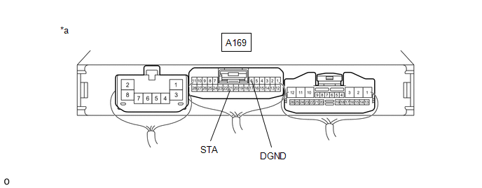
|
*a | Component with harness connected (Engine Stop and Start ECU) |
- | - |
(a) Using the GTS, perform Active Test.
Powertrain > Stop and Start > Active Test|
Tester Display |
|---|
| Starter Motor Drive Magnet Switch(Hood Close) |
(b) Measure the voltage according to the value(s) in the table below.
Click here
Standard Voltage:
|
Tester Connection | Condition |
Specified Condition |
|---|---|---|
|
A169-21 (STA) - A169-6 (DGND) |
Performing Active Test, while cranking. |
6 to 14 V |
| (c) Using an oscilloscope, measure the waveform immediately after starting.
OK: Voltage and waveform both normal |
|
| OK | | INSPECT ENGINE (PRE-IGNITION, SFI SYSTEM, POOR STARTABILITY) |
| NG | | REPLACE ENGINE STOP AND START ECU |
| 13. |
CHECK DATA POINTS (ENGINE SPEED) |
(a) Select a vehicle control history (RoB) item to display the data from the time of control.
(b) Check the output data.
HINT:
- Checking the freeze frame data allows the vehicle conditions at the time of detection to be confirmed.
- As Vehicle Control History (RoB) may be overwritten whenever the trigger conditions are met, make sure to save the Vehicle Control History (RoB) data before performing any inspections.
|
Result | Proceed to |
|---|---|
|
When Starter Motor is ON, there is even 1 point at which Engine Speed < 300 rpm |
A |
| None of the above conditions are met |
B |
| A |
| INSPECT STARTER SYSTEM |
|
| 14. |
CHECK OPERATION |
(a) Check how long it took the engine to stall after turning the starter off.
|
Result | Proceed to |
|---|---|
|
After starter turned off, engine immediately stalls. HINT: Engine stalls within 2 seconds. |
A |
| After starter turned off, engine stalls after a time. |
B |
| A |
| GO TO SFI SYSTEM (ENGINE DIFFICULT TO START) |
| B |
| GO TO SFI SYSTEM (ENGINE STALLS) |


