Toyota Corolla Cross: A/F (O2) Sensor Positive Current Control Bank 1 Sensor 1 Circuit Short to Ground (P223711,P223712,P223713,P223716,P223717,P22371B,P225111,P225112)
DESCRIPTION
Refer to DTC P003012.
Click here
.gif)
HINT:
Although the DTC titles say O2 sensor, these DTCs relate to the air fuel ratio sensor (sensor 1).
|
DTC No. | Detection Item |
DTC Detection Condition | Trouble Area |
MIL | Note |
|---|---|---|---|---|---|
|
P223711 | A/F (O2) Sensor Positive Current Control Bank 1 Sensor 1 Circuit Short to Ground |
The A1A+ voltage is 1.26 V or less for 5 seconds or more (2 trip detection logic). |
| Comes on |
|
| P223712 |
A/F (O2) Sensor Positive Current Control Bank 1 Sensor 1 Circuit Short to Battery |
The A1A+ voltage is higher than 4.47 V for 5 seconds or more (2 trip detection logic). |
| Comes on |
|
| P223713 |
A/F (O2) Sensor Positive Current Control Bank 1 Sensor 1 Circuit Open |
An open or ground short in the circuit between terminals A1A+ and A1A- of the air fuel ratio sensor (sensor 1) while the engine is running (2 trip detection logic). |
| Comes on |
|
| P223716 |
A/F (O2) Sensor Positive Current Control Bank 1 Sensor 1 Circuit Voltage Below Threshold |
The difference between terminals A1A+ and A1A- is 0.2 V or less for 5 seconds or more (2 trip detection logic). |
| Comes on |
|
| P223717 |
A/F (O2) Sensor Positive Current Control Bank 1 Sensor 1 Circuit Voltage Above Threshold |
The difference between terminals A1A+ and A1A- is higher than 1.04 V for 5 seconds or more (2 trip detection logic). |
| Comes on |
|
| P22371B |
A/F (O2) Sensor Positive Current Control Bank 1 Sensor 1 Circuit Resistance Above Threshold |
The air fuel ratio sensor (sensor 1) impedance is higher than 63 Ω (2 trip detection logic). |
| Comes on |
|
| P225111 |
O2 Sensor Negative Current Control Bank 1 Sensor 1 Circuit Short to Ground |
The A1A- voltage is 1.07 V or less for 5 seconds or more (2 trip detection logic). |
| Comes on |
|
| P225112 |
O2 Sensor Negative Current Control Bank 1 Sensor 1 Circuit Short to Battery |
The A1A- voltage is higher than 3.93 V for 5 seconds or more (2 trip detection logic). |
| Comes on |
|
MONITOR DESCRIPTION
These DTCs are stored when there is an open or short in the air fuel ratio sensor (sensor 1) circuit, or the air fuel ratio sensor (sensor 1) output value is abnormal. The voltage of the air fuel ratio sensor (sensor 1) is monitored while the ignition switch is ON, and the impedance (impedance is an electrical term that indicates the difficulty of flow of current) is checked while the engine is running. If the voltage of the air fuel ratio sensor (sensor 1) is outside the normal range, or the impedance is outside the normal range, the ECM illuminates the MIL and stores a DTC.
MONITOR STRATEGY
|
Related DTCs | P2237: Air fuel ratio sensor (sensor 1) circuit continuity check (circuit open) P2238: Air fuel ratio sensor (sensor 1) impedance check (high impedance) P2238: Air fuel ratio sensor (sensor 1) range check (A1A+ low voltage) P2238: Air fuel ratio sensor (sensor 1) correlation (A1A+ and A1A-) P2239: Air fuel ratio sensor (sensor 1) range check (A1A+ high voltage) P2239: Air fuel ratio sensor (sensor 1) correlation (A1A+ and A1A-) P2252: Air fuel ratio sensor (sensor 1) range check (A1A- low voltage) P2253: Air fuel ratio sensor (sensor 1) range check (A1A- high voltage) |
|
Required Sensors/Components (Main) | Air fuel ratio sensor (sensor 1) |
|
Required Sensors/Components (Related) |
Engine coolant temperature sensor Crankshaft position sensor |
|
Frequency of Operation | Continuous |
|
Duration | 10 seconds: P2237, P2238 (air fuel ratio sensor (sensor 1) high impedance) 5 seconds: Others |
| MIL Operation |
2 driving cycles |
| Sequence of Operation |
None |
TYPICAL ENABLING CONDITIONS
P2237 and P2238|
Monitor runs whenever the following DTCs are not stored |
P0010, P1360, P1362, P1364, P1366, P2614 (Motor drive VVT system control module) P0011 (VVT system - advance) P0012 (VVT system - retard) P0013 (Exhaust VVT oil control solenoid) P0014 (Exhaust VVT system - advance) P0015 (Exhaust VVT system - retard) P0016 (VVT system - misalignment) P0017 (Exhaust VVT system - misalignment) P0031, P0032, P101D (Air fuel ratio sensor (sensor 1) heater) P0037, P0038, P102D (Air fuel ratio sensor (sensor 2) heater) P0087, P0088, P0191, P0192, P0193 (Fuel pressure sensor (for high pressure side)) P0101, P0102, P0103 (Mass air flow meter) P0106, P0107, P0108 (Manifold absolute pressure) P0111, P0112, P0113 (Intake air temperature sensor) P0116, P0117, P0118 (Engine coolant temperature sensor) P0121, P0122, P0123, P0222, P0223, P2135 (Throttle position sensor) P0125 (Insufficient coolant temperature for closed loop fuel control) P0128 (Thermostat) P0136, P013A, P2270, P2271, P22AB, P22AC, P22AD, P22B3, P22B4 (Air fuel ratio sensor (sensor 2)) P0171, P0172 (Fuel system) P0201, P0202, P0203, P0204, P062D, P21CF, P21D0, P21D1, P21D2 (Fuel injector) P0300, P0301, P0302, P0303, P0304 (Misfire) P0327, P0328 (Knock control sensor) P0335, P0337, P0338 (Crankshaft position sensor) P0340, P0342, P0343 (Camshaft position sensor) P0365, P0367, P0368 (Exhaust camshaft position sensor) P0401 (EGR system (closed)) P0441 (EVAP system) P0489, P0490 (EGR control circuit) P0657, P0658, P2102, P2103, P2111, P2112, P2119 (Throttle actuator) P107B, P107C, P107D (Fuel pressure sensor (for low pressure side)) P11EA, P11EC, P11ED, P11EE, P11EF, P219A, P219C, P219D, P219E, P219F (Air-fuel ratio imbalance) P1235 (High pressure fuel pump circuit) P2228, P2229 (Atmospheric pressure sensor) |
|
Monitor runs whenever the following DTCs are not stored |
None |
|
Engine | Running |
| Auxiliary battery voltage |
11 V or higher |
| Ignition switch |
ON |
| Time after ignition switch is off to ON |
5 seconds or more |
|
Fuel cut | Not executed |
|
Auxiliary battery voltage | 10.5 V or higher |
|
Ignition switch | ON |
|
Time after ignition switch is off to ON |
0.5 seconds or more |
|
Air fuel ratio sensor (sensor 1) circuit fail (P2237) |
Not detected |
|
Air fuel ratio sensor (sensor 1) positive/negative current control circuit correlation fail (P2238, P2239) |
Not detected |
|
Air fuel ratio sensor (sensor 1) negative current control circuit range check fail (P2252, P2253) |
Not detected |
|
Auxiliary battery voltage | 10.5 V or higher |
|
Ignition switch | ON |
|
Time after ignition switch is off to ON |
0.5 seconds or more |
|
Air fuel ratio sensor (sensor 1) circuit fail (P2237) |
Not detected |
|
Air fuel ratio sensor (sensor 1) positive current control circuit range check fail (P2238, P2239) |
Not detected |
|
Air fuel ratio sensor (sensor 1) negative current control circuit range check fail (P2252, P2253) |
Not detected |
|
Auxiliary battery voltage | 10.5 V or higher |
|
Ignition switch | ON |
|
Time after ignition switch is off to ON |
0.5 seconds or more |
|
Air fuel ratio sensor (sensor 1) circuit fail (P2237) |
Not detected |
|
Air fuel ratio sensor (sensor 1) positive/negative current control circuit correlation fail (P2238, P2239) |
Not detected |
|
Air fuel ratio sensor (sensor 1) positive current control circuit range check fail (P2238, P2239) |
Not detected |
TYPICAL MALFUNCTION THRESHOLDS
P2237: Air Fuel Ratio Sensor (Sensor 1) Circuit Continuity Check (Circuit Open)|
Air fuel ratio sensor (sensor 1) impedance | Higher than 440 Ω |
|
Air fuel ratio sensor (sensor 1) impedance | Higher than 63 Ω |
|
A1A+ terminal voltage | 1.26 V or less |
|
Difference between A1A+ terminal and A1A- terminal voltage |
0.2 V or less |
|
A1A+ terminal voltage | Higher than 4.47 V |
|
Difference between A1A+ terminal and A1A- terminal voltage |
Higher than 1.04 V |
|
A1A- terminal voltage | 1.07 V or less |
|
A1A- terminal voltage | Higher than 3.93 V |
CONFIRMATION DRIVING PATTERN
HINT:
- After repair has been completed, clear the DTC and then check that the vehicle has returned to normal by performing the following All Readiness check procedure.
Click here
- When clearing the permanent DTCs, refer to the "CLEAR PERMANENT DTC" procedure.
Click here
- Connect the GTS to the DLC3.
- Turn the ignition switch to ON.
- Turn the GTS on.
- Clear the DTCs (even if no DTCs are stored, perform the clear DTC procedure).
- Turn the ignition switch off and wait for at least 30 seconds.
- Put the engine in Inspection Mode (Maintenance Mode).
Click here
- Start the engine and wait 5 minutes or more [A].
- Turn the GTS on.
- Enter the following menus: Powertrain / Engine / Trouble Codes [B].
- Read the pending DTCs.
HINT:
- If a pending DTC is output, the system is malfunctioning.
- If a pending DTC is not output, perform the following procedure.
- Enter the following menus: Powertrain / Engine / Utility / All Readiness.
- Input the DTC: P223711, P223712, P223713, P223716, P223717, P22371B, P225111 or P225112.
- Check the DTC judgment result.
GTS Display
Description
NORMAL
- DTC judgment completed
- System normal
ABNORMAL
- DTC judgment completed
- System abnormal
INCOMPLETE
- DTC judgment not completed
- Perform driving pattern after confirming DTC enabling conditions
HINT:
- If the judgment result is NORMAL, the system is normal.
- If the judgment result is ABNORMAL, the system has a malfunction.
- If the judgment result is INCOMPLETE, idle the engine for 5 minutes and check the DTC judgment result again.
- [A] to [B]: Normal judgment procedure.
The normal judgment procedure is used to complete DTC judgment and also used when clearing permanent DTCs.
- When clearing the permanent DTCs, do not disconnect the cable from the auxiliary battery terminal or attempt to clear the DTCs during this procedure, as doing so will clear the universal trip and normal judgment histories.
WIRING DIAGRAM
Refer to DTC P003012.
Click here
CAUTION / NOTICE / HINT
NOTICE:
- Inspect the fuses for circuits related to this system before performing the following procedure.
- Vehicle Control History may be stored in the hybrid vehicle control ECU assembly if the engine is malfunctioning. Certain vehicle condition information is recorded when Vehicle Control History is stored. Reading the vehicle conditions recorded in both the freeze frame data and Vehicle Control History can be useful for troubleshooting.
Click here
(Select Powertrain in Health Check and then check the time stamp data.)
- If any "Engine Malfunction" Vehicle Control History item has been stored in the hybrid vehicle control ECU assembly, make sure to clear it. However, as all Vehicle Control History items are cleared simultaneously, if any Vehicle Control History items other than "Engine Malfunction" are stored, make sure to perform any troubleshooting for them before clearing Vehicle Control History.
Click here
HINT:
- Sensor 1 refers to the sensor closest to the engine assembly.
- Sensor 2 refers to the sensor farthest away from the engine assembly.
- Refer to "Data List / Active Test" [A/F (O2) Sensor Current B1S1].
Click here
- Read Freeze Frame Data using the GTS. The ECM records vehicle and driving condition information as Freeze Frame Data the moment a DTC is stored. When troubleshooting, Freeze Frame Data can help determine if the vehicle was moving or stationary, if the engine was warmed up or not, if the air fuel ratio was lean or rich, and other data from the time the malfunction occurred.
PROCEDURE
|
1. | CHECK TERMINAL VOLTAGE (AIR FUEL RATIO SENSOR (SENSOR 1) VOLTAGE) |
|
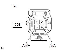
*a | Front view of wire harness connector (to Air Fuel Ratio Sensor (Sensor 1)) |
HINT:
Make sure that the connector is properly connected. If it is not, securely connect it and check for DTCs again.
(a) Disconnect the air fuel ratio sensor (sensor 1) connector.
(b) Turn the ignition switch to ON.
(c) Measure the voltage according to the value(s) in the table below.
Standard Voltage:
|
Tester Connection | Condition |
Specified Condition |
|---|---|---|
|
C56-3 (A1A+) - Body ground |
Ignition switch ON | 2.8 to 3.0 V |
|
C56-4 (A1A-) - Body ground |
Ignition switch ON | 2.3 to 2.7 V |
|
C56-3 (A1A+) - C56-4 (A1A-) |
Ignition switch ON | 0.1 to 0.7 V |
HINT:
Perform "Inspection After Repair" after replacing the air fuel ratio sensor (sensor 1).
Click here
| OK | .gif) | REPLACE AIR FUEL RATIO SENSOR (SENSOR 1) |
|
.gif)
| 2. |
CHECK HARNESS AND CONNECTOR (AIR FUEL RATIO SENSOR (SENSOR 1) - ECM) |
(a) Disconnect the air fuel ratio sensor (sensor 1) connector.
(b) Disconnect the ECM connector.
(c) Measure the resistance according to the value(s) in the table below.
Standard Resistance:
|
Tester Connection | Condition |
Specified Condition |
|---|---|---|
|
C56-1 (HA1A) - C139-9 (HA1A) |
Always | Below 1 Ω |
|
C56-3 (A1A+) - C139-95 (A1A+) |
Always | Below 1 Ω |
|
C56-4 (A1A-) - C139-94 (A1A-) |
Always | Below 1 Ω |
|
C56-1 (HA1A) or C139-9 (HA1A) - Body ground and other terminals |
Always | 10 kΩ or higher |
|
C56-3 (A1A+) or C139-95 (A1A+) - Body ground and other terminals |
Always | 10 kΩ or higher |
|
C56-4 (A1A-) or C139-94 (A1A-) - Body ground and other terminals |
Always | 10 kΩ or higher |
| OK | | REPLACE ECM |
| NG | | REPAIR OR REPLACE HARNESS OR CONNECTOR |
READ NEXT:
 A/F (O2) Sensor Signal Biased/Stuck Lean Bank 1 Sensor 2 Circuit Current Above Threshold (P227019,P227118)
DESCRIPTION Refer to DTC P003612. Click here
HINT: Although the DTC title say O2 sensor, these DTCs relate to the air fuel ratio sensor (sensor 2).
DTC No. Detection Item
DTC Detectio
A/F (O2) Sensor Positive Current Control Bank 1 Sensor 2 Circuit Short to Ground (P22AB11,P22AB12,P22AB13,P22AB16,P22AB17,P22B211,P22B212)
DESCRIPTION Refer to DTC P003612. Click here
HINT: Although the DTC titles say O2 sensor, these DTCs relate to the air fuel ratio sensor (sensor 2).
DTC No. Detection Item
DTC Detecti
Evaporative Emission System Switching Valve Actuator Stuck On (P24507E,P24517F)
DTC SUMMARY
DTC No. Detection Item
DTC Detection Condition Trouble Area
MIL Note
P24507E Evaporative Emission System Switching Valve Actuator Stuck On
Either of t
SEE MORE:
 ECM Communication (C124A00)
DESCRIPTION
If the vehicle information stored by the skid control ECU (brake
actuator assembly) does not match that sent from the ECM or a new skid control ECU
(brake actuator assembly) is installed and the vehicle information has not been
stored, this DTC is stored.
DTC No.
Problem Symptoms Table
PROBLEM SYMPTOMS TABLE
HINT:
Use the table below to help determine the cause of problem symptoms. If
multiple suspected areas are listed, the potential causes of the symptoms are
listed in order of probability in the "Suspected Area" column of the table.
Check each symptom by
