Toyota Corolla Cross: AVC-LAN Circuit
DESCRIPTION
The audio and visual system communicates with each device via AVC-LAN communication. If a malfunction such as a short in a communication line, short to +B or short to ground occurs in the AVC-LAN circuit, communication will stop and the audio and visual system will not operate correctly. The malfunctioning device can be identified if the system returns to normal when the malfunctioning device is disconnected from the AVC-LAN circuit.
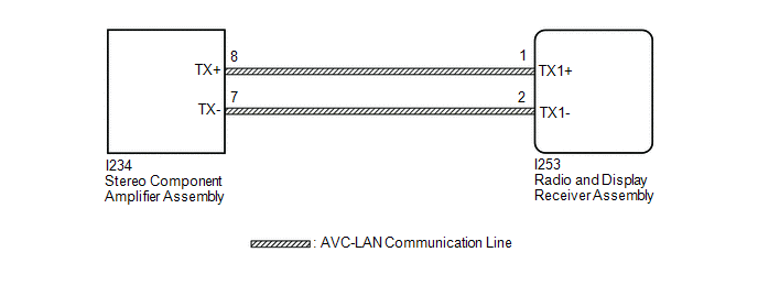
WIRING DIAGRAM
CAUTION / NOTICE / HINT
NOTICE:
Depending on the parts that are replaced during vehicle inspection or maintenance, performing initialization, registration or calibration may be needed.
Click here .gif)
PROCEDURE
|
1. |
REMOVE DEALER INSTALLED OPTIONAL DEVICES (AVC-LAN COMPATIBLE DEVICES) |
(a) Disconnect the connector of each dealer installed optional device (AVC-LAN compatible device) and check if the malfunction continues.
|
Result |
Proceed to |
|---|---|
|
No dealer installed optional devices are installed |
A |
|
The malfunction reoccurs |
|
|
The system returns to normal |
B |
| B | .gif)
|
REPLACE THE DEVICE (OR WIRE HARNESS) |
|
.gif)
|
2. |
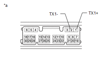
INSPECT RADIO & DISPLAY RECEIVER ASSEMBLY (TX1+, TX1-) |
(a) Remove the radio and display receiver assembly.
Click here
|
(b) Measure the resistance according to the value(s) in the table below. Standard Resistance:
|
|
| NG |
|
REPLACE RADIO & DISPLAY RECEIVER ASSEMBLY |
|
|
3. |
CHECK HARNESS AND CONNECTOR (AVC-LAN CIRCUIT) |
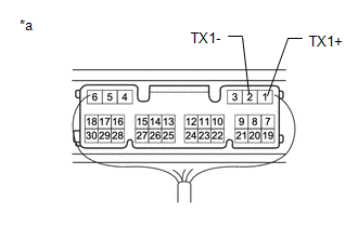
(a) Disconnect the I253 radio and display receiver assembly connector.
(b) Disconnect the I234 stereo component amplifier assembly connector.
(c) Measure the resistance according to the value(s) in the table below.
Standard Resistance:
|
Tester Connection |
Condition |
Specified Condition |
|---|---|---|
|
I253-1 (TX1+) - I234-8 (TX+) |
Always |
Below 1 Ω |
|
I253-2 (TX1-) - I234-7 (TX-) |
Always |
Below 1 Ω |
|
I253-1 (TX1+) or I234-8 (TX+) - Body ground |
Always |
10 kΩ or higher |
|
I253-2 (TX1-) or I234-7 (TX-) - Body ground |
Always |
10 kΩ or higher |
| NG |
|
REPAIR OR REPLACE HARNESS OR CONNECTOR |
|
|
4. |
CHECK AVC-LAN COMPATIBLE DEVICES (DISCONNECT CONNECTOR) |
(a) Disconnect the connector of each AVC-LAN connected device and check if the malfunction continues.
|
Result |
Proceed to |
|---|---|
|
The malfunction continues |
A |
|
The system returns to normal (AVC-LAN connected device was malfunctioning) |
B |
| B |
|
REPLACE STEREO COMPONENT AMPLIFIER ASSEMBLY |
|
|
5. |
INSPECT RADIO & DISPLAY RECEIVER ASSEMBLY (AVC-LAN VOLTAGE) |
|
(a) Measure the voltage according to the value(s) in the table below. Standard Voltage:
|
|
| OK |
|
REPLACE RADIO & DISPLAY RECEIVER ASSEMBLY |
| NG |
|
REPAIR OR REPLACE HARNESS OR MALFUNCTIONING AVC-LAN CONNECTED DEVICE |


