Toyota Corolla Cross: Removal
REMOVAL
CAUTION / NOTICE / HINT
COMPONENTS (REMOVAL)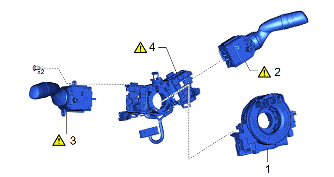
|
Procedure | Part Name Code |
.png) |
.png) |
 |
|---|---|---|---|---|---|
|
1 | SPIRAL CABLE SUB-ASSEMBLY |
84306 | - |
- | - |
|
2 | WINDSHIELD WIPER SWITCH ASSEMBLY |
84650 |
|
- | - |
|
3 | TURN SIGNAL SWITCH |
84329 |
|
- | - |
|
4 | STEERING WHEEL SWITCH HOUSING |
84319 |
|
- | - |
CAUTION / NOTICE / HINT
HINT:
When the cable is disconnected/reconnected to the auxiliary battery terminal, systems temporarily stop operating. However, each system has a function that completes learning the first time the system is used.
- Learning completes when vehicle is driven
Effect/Inoperative Function When Necessary Procedures are not Performed
Necessary Procedures
Link
*1: for Gasoline Model Front Camera System
Drive the vehicle straight ahead at 15 km/h (10 mph) or more for 1 second or more.
.gif)
Stop and start system*1
Drive the vehicle until stop and start control is permitted (approximately 5 to 60 minutes)
- Learning completes when vehicle is operated normally
Effect/Inoperative Function When Necessary Procedures are not Performed
Necessary Procedures
Link
Power door lock control system
- Back door opener
Perform door unlock operation with door control switch or electrical key transmitter sub-assembly switch.
Power back door system
Fully close the back door by hand.
HINT:
Initialization is not necessary if the above procedures are performed while the back door is closed.
Air conditioning system
After the ignition switch is turned to ON, the servo motor standard position is recognized.
-
PROCEDURE
1. REMOVE SPIRAL CABLE SUB-ASSEMBLY
Click here
2. REMOVE WINDSHIELD WIPER SWITCH ASSEMBLY
|
|
Click here |
3. REMOVE TURN SIGNAL SWITCH
|
|
Click here |
4. REMOVE STEERING WHEEL SWITCH HOUSING
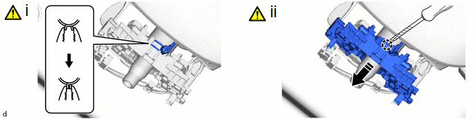
.png) |
Remove in this Direction |
- | - |
(1) Using pliers, expand the clamp as shown in the illustration.
(2) While holding the clamp expanded, using a screwdriver with its tip wrapped with protective tape, disengage the claw to remove the steering wheel switch housing as shown in the illustration.


