Toyota Corolla Cross: Inspection
INSPECTION
PROCEDURE
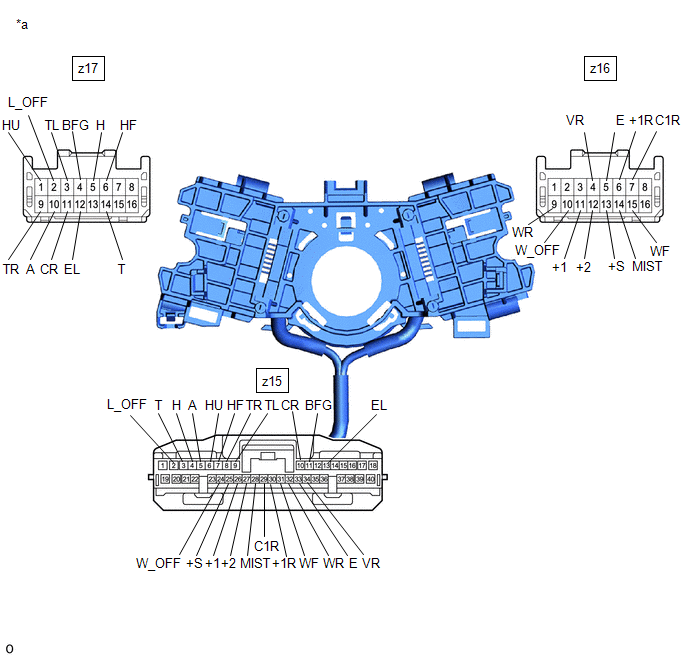
1. INSPECT STEERING WHEEL SWITCH HOUSING
(a) Resistance Check.
|
*a | Component without harness connected (Steering Wheel Switch Housing) |
- | - |
(1) Measure the resistance according to the value(s) in the table below.
Standard Resistance:
Light Switch Circuit|
Tester Connection | Condition |
Specified Condition |
|---|---|---|
|
z17-14 (T) - z15-3 (T) |
Always | Below 1 Ω |
|
z17-5 (H) - z15-4 (H) |
Always | Below 1 Ω |
|
z17-10 (A) - z15-5 (A) |
Always | Below 1 Ω |
|
z17-1 (HU) - z15-6 (HU) |
Always | Below 1 Ω |
|
z17-6 (HF) - z15-7 (HF) |
Always | Below 1 Ω |
|
z17-9 (TR) - z15-8 (TR) |
Always | Below 1 Ω |
|
z17-3 (TL) - z15-9 (TL) |
Always | Below 1 Ω |
|
z17-11 (CR) - z15-10 (CR) |
Always | Below 1 Ω |
|
z17-4 (BFG) - z15-11 (BFG) |
Always | Below 1 Ω |
|
z17-2 (L_OFF) - z15-2 (L_OFF) |
Always | Below 1 Ω |
|
z17-12 (EL) - z15-13 (EL) |
Always | Below 1 Ω |
|
Tester Connection | Condition |
Specified Condition |
|---|---|---|
|
z16-10 (W_OFF) - z15-24 (W_OFF) |
Always | Below 1 Ω |
|
z16-13 (+S) - z15-25 (+S) |
Always | Below 1 Ω |
|
z16-11 (+1) - z15-26 (+1) |
Always | Below 1 Ω |
|
z16-12 (+2) - z15-27 (+2) |
Always | Below 1 Ω |
|
z16-14 (MIST) - z15-28 (MIST) |
Always | Below 1 Ω |
|
z16-7 (C1R) - z15-29 (C1R) |
Always | Below 1 Ω |
|
z16-6 (+1R) - z15-30 (+1R) |
Always | Below 1 Ω |
|
z16-15 (WF) - z15-31 (WF) |
Always | Below 1 Ω |
|
z16-9 (WR) - z15-32 (WR) |
Always | Below 1 Ω |
|
z16-5 (E) - z15-33 (E) |
Always | Below 1 Ω |
|
z16-4 (VR) - z15-34 (VR) |
Always | Below 1 Ω |
If the result is not as specified, replace the steering wheel switch housing.


