Toyota Corolla Cross: Removal
REMOVAL
CAUTION / NOTICE / HINT
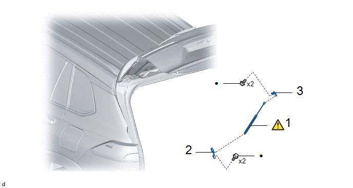
COMPONENTS (REMOVAL)
|
Procedure | Part Name Code |
.png) |
.png) |
.png) |
|
1 | BACK DOOR STAY ASSEMBLY |
68960B |
.gif) |
- | - |
|
2 | BACK DOOR DAMPER STAY UPPER BRACKET |
68946 | - |
- | - |
|
3 | BACK DOOR DAMPER STAY LOWER BRACKET |
68948 | - |
- | - |
CAUTION / NOTICE / HINT
HINT:
- Use the same procedure for the RH side and LH side.
- The following procedure is for the LH side.
PROCEDURE
1. REMOVE BACK DOOR STAY ASSEMBLY
|
|
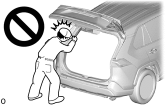
CAUTION:
- Do not perform work if the back door is not securely supported.
- The back door could fall, resulting in injury.
NOTICE:
- Avoid touching the piston rod as much as possible to prevent foreign matter from attaching to it. Be sure to hold the cylinder while servicing.
- Do not wear cotton gloves or other similar materials when handling the piston rod. Fibers may attach to the rod and result in gas leaks.
- Do not apply any horizontal load to the door stay in order to prevent the piston rod from deforming.
|

(1) Using a screwdriver with its tip wrapped in protective tape, slightly raise the 2 stop rings and remove the back door stay assembly.
CAUTION:
Remove the back door stay assembly while supporting the back door by hand.
NOTICE:
Do not remove the stop rings from the back door stay assembly. Raise the stop rings just enough to allow the ball joints to be disengaged.
2. REMOVE BACK DOOR DAMPER STAY UPPER BRACKET

3. REMOVE BACK DOOR DAMPER STAY LOWER BRACKET

READ NEXT:
INSTALLATION CAUTION / NOTICE / HINT COMPONENTS (INSTALLATION)
Procedure Part Name Code
1 BACK DOOR DAMPER STAY LOWER BRACKET
68948
- -
2
DISPOSAL PROCEDURE 1. DISPOSE OF BACK DOOR STAY ASSEMBLY
NOTICE: Make sure the piston rods are in the fully extended stake before performing work.
(a) Secure the back door stay assembly horizontally
RemovalREMOVAL CAUTION / NOTICE / HINT COMPONENTS (REMOVAL)
Procedure Part Name Code
1 BACK DOOR WEATHERSTRIP
67881A
- -
● Non-reusable
SEE MORE:
INSTALLATION CAUTION / NOTICE / HINT COMPONENTS (INSTALLATION)
Procedure Part Name Code
1 TURN SIGNAL SWITCH
84329 -
- -
2 UPPER STEERING COLUMN COVER
45286B -
- -
3 LOWER STEERING COLUMN COVER
45287
-
Your vehicle is equipped with a
tire pressure warning system
that uses tire pressure warning
valves and transmitters to detect low tire inflation pressure before
serious problems arise.
The tire pressure warning system
of this vehicle adopts a
2-type warning system.
When "Adjust Pressure" is
dis


