Toyota Corolla Cross: Removal
REMOVAL
CAUTION / NOTICE / HINT
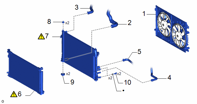
COMPONENTS (REMOVAL)
|
Procedure | Part Name Code |
.png) |
.png) |
 |
|---|---|---|---|---|---|
|
1 | FAN WITH MOTOR ASSEMBLY |
- | - |
- | - |
|
2 | INLET HYBRID RADIATOR HOSE |
G922H | - |
- | - |
|
3 | NO. 1 WATER BY-PASS HOSE |
16261G | - |
- | - |
|
4 | INLET NO. 1 INVERTER COOLING HOSE |
G922AA | - |
- | - |
|
5 | NO. 1 RADIATOR HOSE |
16571C | - |
- | - |
|
6 | COOLER CONDENSER ASSEMBLY |
884A0 |
|
- | - |
|
7 | RADIATOR ASSEMBLY |
16400 |
|
- | - |
|
8 | RADIATOR SUPPORT CUSHION |
16523A | - |
- | - |
|
9 | LOWER RADIATOR SUPPORT |
16535 | - |
- | - |
|
10 | RADIATOR DRAIN COCK PLUG |
16400B | - |
- | - |
|
● | Non-reusable part |
- | - |
PROCEDURE
1. REMOVE FAN WITH MOTOR ASSEMBLY
Click here
.gif)
2. DISCONNECT INLET HYBRID RADIATOR HOSE

3. DISCONNECT NO. 1 WATER BY-PASS HOSE

4. DISCONNECT INLET NO. 1 INVERTER COOLING HOSE

5. DISCONNECT NO. 1 RADIATOR HOSE

6. REMOVE COOLER CONDENSER ASSEMBLY
.png) |
NOTICE: Make sure not to damage the cooler condenser assembly when separating the cooler condenser assembly. |

7. REMOVE RADIATOR ASSEMBLY
.png) |
NOTICE: Do not apply excessive force to the cooler condenser assembly or pipe when removing the radiator assembly. |

8. REMOVE RADIATOR SUPPORT CUSHION

9. REMOVE LOWER RADIATOR SUPPORT

10. REMOVE RADIATOR DRAIN COCK PLUG


