Toyota Corolla Cross: Relay
On-vehicle Inspection
ON-VEHICLE INSPECTION
PROCEDURE
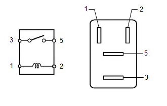
1. INSPECT FAN NO. 1 RELAY
| (a) Measure the resistance according to the value(s) in the table below.
Standard Resistance: |
Tester Connection | Condition |
Specified Condition | |
3 - 5 | Auxiliary battery voltage not applied between terminals 1 and 2 |
10 kΩ or higher | |
3 - 5 | Auxiliary battery voltage applied between terminals 1 and 2 |
Below 1 Ω | | |
(b) If the result is not as specified, replace the FAN NO. 1 relay.
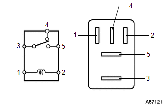
2. INSPECT FAN NO. 2 RELAY
| (a) Measure the resistance according to the value(s) in the table below.
Standard Resistance: |
Tester Connection | Condition |
Specified Condition | |
3 - 4 | Auxiliary battery voltage not applied between terminals 1 and 2 |
Below 1 Ω | |
3 - 4 | Auxiliary battery voltage applied between terminals 1 and 2 |
10 kΩ or higher | |
3 - 5 | Auxiliary battery voltage not applied between terminals 1 and 2 |
10 kΩ or higher | |
3 - 5 | Auxiliary battery voltage applied between terminals 1 and 2 |
Below 1 Ω | | |
(b) If the result is not as specified, replace the FAN NO. 2 relay.
3. INSPECT FAN NO. 3 RELAY
| (a) Measure the resistance according to the value(s) in the table below.
Standard Resistance: |
Tester Connection | Condition |
Specified Condition | |
3 - 5 | Auxiliary battery voltage not applied between terminals 1 and 2 |
10 kΩ or higher | |
3 - 5 | Auxiliary battery voltage applied between terminals 1 and 2 |
Below 1 Ω | | |
(b) If the result is not as specified, replace the FAN NO. 3 relay.
READ NEXT:
REMOVAL CAUTION / NOTICE / HINT COMPONENTS (REMOVAL)
Procedure Part Name Code
1 ENGINE WATER PUMP ASSEMBLY (WATER INLET HOUSING)
16032 -
- -
INSPECTION PROCEDURE 1. INSPECT WATER INLET WITH THERMOSTAT SUB-ASSEMBLY
CAUTION:
Do not put your hands into the water that has been heated for the inspection.
Touching the heated water
SEE MORE:
REASSEMBLY CAUTION / NOTICE / HINT COMPONENTS (REASSEMBLY)
Procedure Part Name Code
1 REAR SIDE MARKER LIGHT BULB
81550S -
- -
2 REAR SIDE MARKER LIGHT SOCKET
- -
- -
*A for Bulb Type Clearance Light
- -
*1
INSPECTION PROCEDURE 1. INSPECT SIDE TURN SIGNAL LIGHT ASSEMBLY LH
(a) Check that the side turn signal light assembly LH.
(1) Apply auxiliary battery voltage to the side turn signal light assembly LH and check that the light comes on.
OK:
Tester Connection Specified Condition