Toyota Corolla Cross: Brake Pressure Sensor "A" / Brake Switch "A" Signal Compare Failure (C117B62)
DESCRIPTION
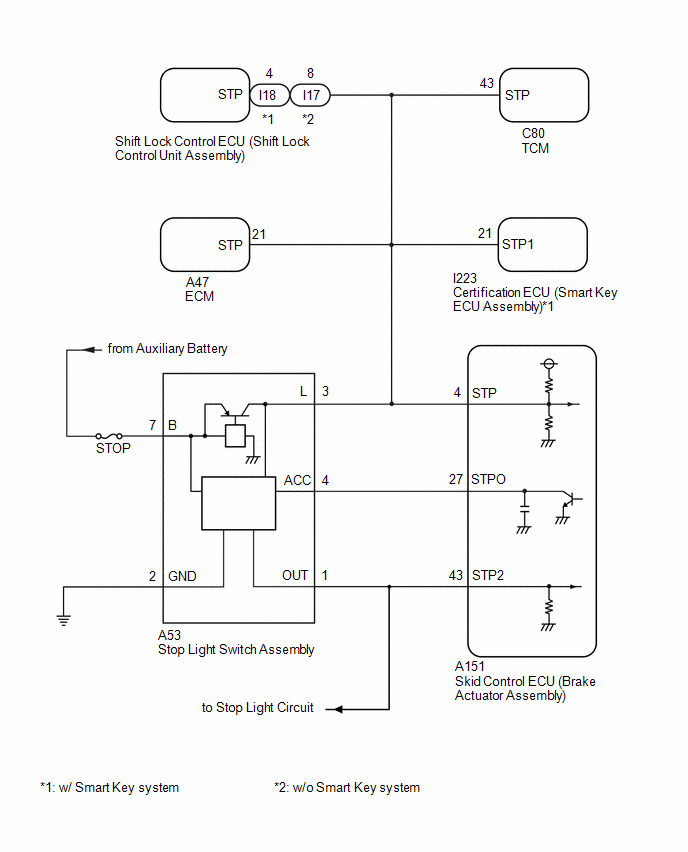
The skid control ECU (brake actuator assembly) receives stop light switch assembly signals and uses them to determine whether or not the brakes are applied.
When the brake pedal is depressed and no signal is received from the stop light switch assembly, this DTC is output.
|
DTC No. |
Detection Item |
DTC Detection Condition |
Trouble Area |
|---|---|---|---|
|
C117B62 |
Brake Pressure Sensor "A" / Brake Switch "A" Signal Compare Failure |
Either of the following is detected when the vehicle speed of 3 km/h (2 mph) or more:
|
|
WIRING DIAGRAM
CAUTION / NOTICE / HINT
NOTICE:
Inspect the fuses for circuits related to this system before performing the following procedure.
PROCEDURE
|
1. |
READ VALUE USING GTS (MASTER CYLINDER SENSOR) |
(a) Check the Data List using the GTS.
Chassis > Brake/EPB > Data List|
Tester Display |
Measurement Item |
Range |
Normal Condition |
Diagnostic Note |
|---|---|---|---|---|
|
Master Cylinder Sensor 1 |
Master cylinder pressure sensor pressure (value detected by ECU) |
Min.: -1.00 MPa, Max.: 23.99 MPa |
Brake pedal released: -1.00 to 0.00 MPa |
Reading increases when brake pedal is depressed |
|
Tester Display |
|---|
|
Master Cylinder Sensor 1 |
(b) Check the value of Data List item Master Cylinder Sensor 1 when the brake pedal is released.
OK:
The value of Data List item Master Cylinder Sensor 1 when the brake pedal is released is less than 0.15 MPa.
| NG | .gif)
|
GO TO STEP 4 |
|
.gif)
|
2. |
CHECK HARNESS AND CONNECTOR (STOP LIGHT SWITCH ASSEMBLY SIGNAL INPUT CIRCUIT) |
|
(a) Make sure that there is no looseness at the locking part and the connecting part of the connector. OK: The connector is securely connected. |
|
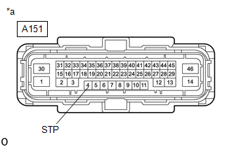
(b) Disconnect the A151 skid control ECU (brake actuator assembly) connector.
(c) Check both the connector case and the terminals for deformation and corrosion.
OK:
No deformation or corrosion.
(d) Measure the voltage according to the value(s) in the table below.
Standard Voltage:
|
Tester Connection |
Condition |
Specified Condition |
|---|---|---|
|
A151-4 (STP) - Body ground |
Brake pedal depressed |
11 to 14 V |
| OK |
|
REPLACE BRAKE ACTUATOR ASSEMBLY |
|
|
3. |
CHECK HARNESS AND CONNECTOR (STOP LIGHT SWITCH ASSEMBLY - BRAKE ACTUATOR ASSEMBLY) |
(a) Make sure that there is no looseness at the locking part and the connecting part of the connector.
OK:
The connector is securely connected.
(b) Disconnect the A151 skid control ECU (brake actuator assembly) connector.
(c) Disconnect the A53 stop light switch assembly connector.
(d) Check both the connector case and the terminals for deformation and corrosion.
OK:
No deformation or corrosion.
(e) Measure the resistance according to the value(s) in the table below.
Standard Resistance:
|
Tester Connection |
Condition |
Specified Condition |
|---|---|---|
|
A53-3 (L) - A151-4 (STP) |
Always |
Below 1 Ω |
|
A53-3 (L) or A151-4 (STP) - Body ground and other terminals |
Always |
10 kΩ or higher |
| OK |
|
REPLACE STOP LIGHT SWITCH ASSEMBLY |
| NG |
|
REPAIR OR REPLACE HARNESS OR CONNECTOR |
|
4. |
CHECK DTC |
(a) Read the DTCs using the GTS.
Chassis > Brake/EPB > Trouble Codes|
Result |
Proceed to |
|---|---|
|
C117B62 and C05401C, C054028, C054029, C054031, C054049 and/or C054096 are output simultaneously |
A |
|
C117B62 is output |
B |
| A |
|
REPAIR CIRCUITS INDICATED BY OUTPUT DTCS |
| B |
|
GO TO BRAKE SYSTEM Inspect brake pedal free play: Click here
Inspect brake booster assembly: Click here
|
.gif)
READ NEXT:
 ECM Communication (C124A00)
DESCRIPTION
If the vehicle information stored by the skid control ECU (brake
actuator assembly) does not match that sent from the ECM or a new skid control ECU
(brake actuator assembly) is instal
Left Front Wheel ABS Hold Solenoid Control Circuit Short to Battery (C12A512,...,C12B049)
DESCRIPTION
The ABS solenoid relay and solenoid valves are built into the
brake actuator assembly.
The front solenoid valve LH controls the brake fluid pressure
of the front wheel cylinder LH of
Right Front Wheel ABS Hold Solenoid Control Circuit Short to Battery (C12BB12,...,C12C649)
DESCRIPTION
The ABS solenoid relay and solenoid valves are built into the
brake actuator assembly.
The front solenoid valve RH controls the brake fluid pressure
of the front wheel cylinder RH of
SEE MORE:
 A/F (O2) Sensor Positive Current Control Bank 1 Sensor 1 Circuit Short to Ground (P223711,P223712,P223713,P223716,P223717,P22371B,P225111,P225112)
DESCRIPTION Refer to DTC P003012. Click here
HINT: Although the DTC titles say O2 sensor, these DTCs relate to the air fuel ratio sensor (sensor 1).
DTC No. Detection Item
DTC Detection Condition Trouble Area
MIL Note
P223711 A/F (O2) Sensor Positive Current Contr
Installation
INSTALLATION CAUTION / NOTICE / HINT COMPONENTS (INSTALLATION)
Procedure Part Name Code
1 OUTER MIRROR SWITCH ASSEMBLY
84870A -
- -
2 MULTIPLEX NETWORK MASTER SWITCH ASSEMBLY WITH FRONT DOOR UPPER ARMREST BASE PANEL
- -
- -
