Toyota Corolla Cross: Removal
REMOVAL
CAUTION / NOTICE / HINT
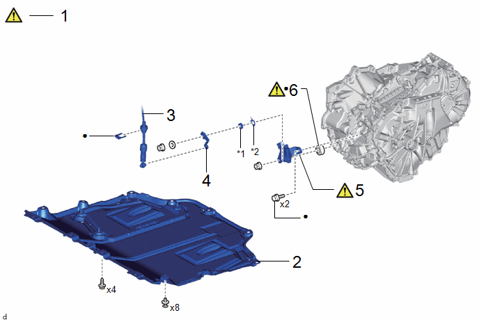
COMPONENTS (REMOVAL)
|
Procedure |
Part Name Code |
.png) |
.png) |
.png) |
|
|---|---|---|---|---|---|
|
1 |
SECURE VEHICLE |
- |
|
- |
- |
|
2 |
NO. 1 ENGINE UNDER COVER ASSEMBLY |
51410 |
- |
- |
- |
|
3 |
TRANSMISSION CONTROL CABLE ASSEMBLY |
33820B |
- |
- |
- |
|
4 |
TRANSMISSION CONTROL SHAFT LEVER |
35572D |
- |
- |
- |
|
5 |
SHIFT LEVER POSITION SENSOR |
89451A |
|
- |
- |
|
6 |
SHIFT LEVER POSITION SENSOR SEAL |
- |
|
- |
- |
|
*1 |
LOCK NUT |
*2 |
LOCK PLATE |
|
● |
Non-reusable part |
- |
- |
PROCEDURE
1. SECURE VEHICLE
.png)
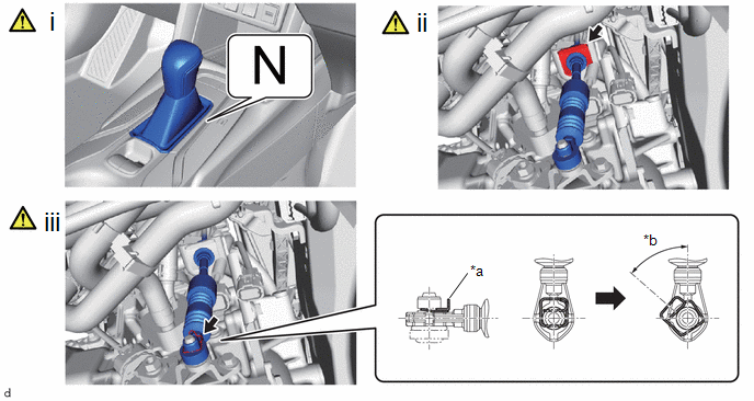
(1) Fully apply the parking brake and chock a wheel.
CAUTION:
- Make sure to apply the parking brake and chock a wheel before performing this procedure.
- If the vehicle is not secure and the shift lever is moved to N, the vehicle may suddenly move, possibly resulting in an accident or serious injury.
2. REMOVE NO. 1 ENGINE UNDER COVER ASSEMBLY
Click here .gif)
3. DISCONNECT TRANSMISSION CONTROL CABLE ASSEMBLY

|
*a |
Clip |
*b |
45° to 60° |
(1) Shift the shift lever to N.
(2) Remove the clip.
(3) Disconnect the transmission control cable with the clip integrated with it.
4. REMOVE TRANSMISSION CONTROL SHAFT LEVER

5. REMOVE SHIFT LEVER POSITION SENSOR

|
*1 |
Lock Plate |
*2 |
Lock Nut |
(1) Using a screwdriver with its tip wrapped with protective tape, pry out the tabs of the lock plate.
(2) Remove the lock nut and lock plate from the shift lever position sensor.
(3) Remove the 2 bolts and shift lever position sensor from the hybrid vehicle transaxle assembly.
6. REMOVE SHIFT LEVER POSITION SENSOR SEAL
.png) |
HINT: Perform this procedure only when replacement of the shift lever position sensor seal is necessary. |

(1) Using a screwdriver with its tip wrapped in protective tape, remove the shift lever position sensor seal from the hybrid vehicle transaxle assembly.
NOTICE:
When removing the shift lever position sensor seal, make sure not to damage the parking lock shaft or transaxle case.


