Toyota Corolla Cross: Inspection
INSPECTION
PROCEDURE
1. INSPECT SHIFT LEVER POSITION SENSOR
|
(a) Measure the resistance according to the value(s) in the table below.
Standard Resistance:
|
Tester Connection
|
Condition
|
Specified Condition
|
|
7 (+B) - 3 (PR)
|
Shift lever in P
|
Below 1 Ω
|
|
7 (+B) - 4 (PNB)
|
Below 1 Ω
|
|
7 (+B) - 8 (P)
|
Below 1 Ω
|
|
7 (+B) - 1 (DB1), 2 (N), 6 (DB2) or 9 (R)
|
Shift lever in P
|
10 kΩ or higher
|
|
7 (+B) - 3 (PR)
|
Shift lever in R
|
Below 1 Ω
|
|
7 (+B) - 9 (R)
|
Below 1 Ω
|
|
7 (+B) - 1 (DB1), 2 (N), 4 (PNB), 6 (DB2) or 8 (P)
|
Shift lever in R
|
10 kΩ or higher
|
|
7 (+B) - 2 (N)
|
Shift lever in N
|
Below 1 Ω
|
|
7 (+B) - 4 (PNB)
|
Below 1 Ω
|
|
7 (+B) - 1 (DB1), 3 (PR), 6 (DB2), 8 (P) or 9 (R)
|
Shift lever in N
|
10 kΩ or higher
|
|
7 (+B) - 1 (DB1)
|
Shift lever in D
|
Below 1 Ω
|
|
7 (+B) - 6 (DB2)
|
Below 1 Ω
|
|
7 (+B) - 2 (N), 3 (PR), 4 (PNB), 8 (P) or 9 (R)
|
Shift lever in D
|
10 kΩ or higher
|
|
7 (+B) - 1 (DB1)
|
Shift lever in B
|
Below 1 Ω
|
|
7 (+B) - 4 (PNB)
|
Below 1 Ω
|
|
7 (+B) - 6 (DB2)
|
Below 1 Ω
|
|
7 (+B) - 2 (N), 3 (PR), 8 (P) or 9 (R)
|
Shift lever in B
|
10 kΩ or higher
|
HINT:
The shift lever position sensor connector (shift lever position sensor
side) does not have a terminal 5.
If the result is not as specified, replace the shift lever position sensor.
|
|
|
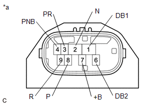
*a
|
Component without harness connected
(Shift Lever Position Sensor)
|
|
|
READ NEXT:
ADJUSTMENT
PROCEDURE
1. SECURE VEHICLE
(a) Fully apply the parking brake and chock a wheel.
CAUTION:
Make sure to apply the parking brake and chock a wheel before performing
this procedure.
INSTALLATION
CAUTION / NOTICE / HINT
COMPONENTS (INSTALLATION)
Procedure
Part Name Code
1
SHIFT LEVER POSITION SENSOR S
SEE MORE:
INSTALLATION
CAUTION / NOTICE / HINT
COMPONENTS (INSTALLATION)
Procedure
Part Name Code
1
SPARK PLUG
19100P
-
-
2
IGNITION COIL ASSEMBLY
INSTALLATION CAUTION / NOTICE / HINT COMPONENTS (INSTALLTION)
Procedure Part Name Code
1 HORN BUTTON ASSEMBLY
45130
- -
2 CABLE TO NEGATIVE AUXILIARY BATTERY TERMINAL
- -
- -
3 INSPECT HORN BUTTON ASSEM


