Toyota Corolla Cross: Rear Power Window RH Auto Up / Down Function does not Operate with Rear Power Window Switch RH
DESCRIPTION
If the manual up and down functions operate normally but the auto up and down functions do not, the power window control system may be in fail-safe mode.
If power window initialization has not been performed, the auto up and down functions will not operate.
WIRING DIAGRAM
Click here .gif)
CAUTION / NOTICE / HINT
NOTICE:
- If the power window regulator motor assembly (for rear RH door) has been replaced with a new one, initialize the power window control system.
Click here
- Check that power window system customize settings "RR Window Auto Up Function" and "RR Window Auto Down Function" are set to "ON" before performing the following procedure.
Click here
- After the catch protection function has operated, the auto up function will not operate the first time the power window auto up switch is operated. The auto up function will operate normally after the first power window switch operation.
- Before replacing the main body ECU (multiplex network body ECU), refer to Registration.*1
- for HEV Model:
Click here
- for Gasoline Model:
Click here
- *1: w/ Smart Key System
- for HEV Model:
HINT:
If the pulse sensor built into the power window regulator motor assembly (for rear RH door) is malfunctioning, the power window control system will enter fail-safe mode. The remote up and down and auto up and down functions cannot be operated during fail-safe mode. However, the power window can be closed by holding the rear power window regulator switch assembly (for rear RH door) at the auto up position, and opened manually by pushing down the rear power window regulator switch assembly (for rear RH door).
PROCEDURE
| 1. |
READ VALUE USING GTS |
(a) Read the Data List according to the display on the GTS.
Body Electrical > Main Body > Data List|
Tester Display | Measurement Item |
Range | Normal Condition |
Diagnostic Note |
|---|---|---|---|---|
|
RR Door Power Window AUTO Switch |
Rear RH door power window auto switch |
OFF or ON | OFF: Manual down switch not being operated ON: Manual down switch being operated |
- |
|
Tester Display |
|---|
| RR Door Power Window AUTO Switch |
OK:
On the GTS screen, ON or OFF is displayed accordingly.
| NG | .gif) | GO TO STEP 4 |
|
.gif)
| 2. |
PERFORM INITIALIZATION |
(a) Initialize the power window regulator motor assembly (for rear RH door).
Click here
|
| 3. |
CHECK POWER WINDOW CONTROL SYSTEM (AUTO UP / DOWN FUNCTION) |
(a) Check that the rear RH door power window moves when the auto up and down functions of the rear power window regulator switch assembly (for rear RH door) are operated.
Click here
OK:
Rear RH door auto up and down functions are normal.
| OK | | END (PROBLEM DUE TO INITIALIZATION FAILURE) |
| NG | | REPLACE POWER WINDOW REGULATOR MOTOR ASSEMBLY (for Rear RH Door) |
| 4. |
INSPECT REAR POWER WINDOW REGULATOR SWITCH ASSEMBLY (for Rear RH Door) |
Click here
| NG | | REPLACE REAR POWER WINDOW REGULATOR SWITCH ASSEMBLY (for Rear RH Door) |
|
| 5. |
CHECK HARNESS AND CONNECTOR (REAR POWER WINDOW REGULATOR SWITCH ASSEMBLY - POWER WINDOW REGULATOR MOTOR ASSEMBLY (for Rear RH Door)) |
(a) Disconnect the M3 power window regulator motor assembly (for rear RH door) connector.
(b) Measure the resistance according to the value(s) in the table below.
Standard Resistance:
|
Tester Connection | Condition |
Specified Condition |
|---|---|---|
|
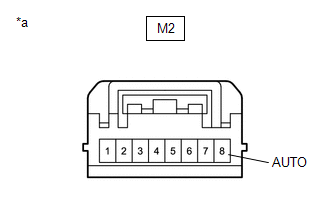
M2-8 (AUTO) - M3-4 (AUTO) |
Always | Below 1 Ω |
|
M2-8 (AUTO) or M3-4 (AUTO) - Body ground |
Always | 10 kΩ or higher |
| NG | | REPAIR OR REPLACE HARNESS OR CONNECTOR |
|
| 6. |
CHECK POWER WINDOW REGULATOR MOTOR ASSEMBLY (for Rear RH Door) |
(a) Connect the M3 power window regulator motor assembly (for rear RH door) connector.
| (b) Measure the voltage according to the value(s) in the table below. Standard Voltage:
|
|
| OK | | REPLACE MAIN BODY ECU (MULTIPLEX NETWORK BODY ECU) for RHD: Click here |
| NG | | REPLACE POWER WINDOW REGULATOR MOTOR ASSEMBLY (for Rear RH Door) |
READ NEXT:
 All Power Windows do not Operate with Driver Side Door Key Cylinder or Wireless Transmitter
DESCRIPTION Wireless Transmitter-linked Function
When a key switch is pushed: 1) the door control receiver receives the wireless door lock signal; 2) the door control receiver sends a signal to the
Key-off Operation Function Operates even if Operating Conditions are not Satisfied
DESCRIPTION When the front doors are closed, each power window regulator motor assembly can be operated for approximately 45 seconds after the ignition switch is turned from ON to off by receiving ope
Auto Up Operation does not Fully Close Power Window (Jam Protection Function is Activated)
DESCRIPTION If a door glass does not slide smoothly or a power window regulator motor assembly or door window regulator sub-assembly does not operate smoothly, the jam protection function may be trigg
SEE MORE:
 Parts Location
PARTS LOCATION ILLUSTRATION
*1 FUEL PUMP (for Low Pressure Side)
*2 MASS AIR FLOW METER SUB-ASSEMBLY
*3 ECM
*4 NO. 1 ENGINE ROOM RELAY BLOCK
*5 FUEL PUMP CONTROL ECU
*6 CANISTER ILLUSTRATION
*1 AIR FUEL RATIO SENSOR (Sensor 2)
Removal
REMOVAL
CAUTION / NOTICE / HINT
COMPONENTS (REOVAL)
Procedure
Part Name Code
1
PERFORM RESOLVER INITIALIZATION
-
-
-
2
REAR TRACTION MOTOR CABLE
