Toyota Corolla Cross: Low or High Power Supply Voltage (C1241)
DESCRIPTION
If a malfunction in the power source circuit occurs, or a malfunction in communication between the skid control ECU (brake actuator assembly) and 4WD ECU assembly occurs, the 4WD ECU assembly will detect a decreased supply voltage malfunction.
|
DTC No. |
Detection Item |
DTC Detection Condition |
Trouble Area |
|---|---|---|---|
|
C1241 |
Low or High Power Supply Voltage |
|
|
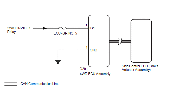
WIRING DIAGRAM
CAUTION / NOTICE / HINT
NOTICE:
Inspect the fuses for circuits related to this system before performing the following inspection procedure.
PROCEDURE
|
1. |
CHECK FOR DTC (CAN COMMUNICATION SYSTEM AND ELECTRONICALLY CONTROLLED BRAKE SYSTEM) |
(a) Check if CAN communication system DTCs are output.
Click here .gif)
(b) Start the engine.
(c) Drive the vehicle, accelerate to a speed of 3 km/h (2 mph) or more for 60 seconds or more, and check if the speed sensor DTC (electronically controlled brake system DTC) is output.
Chassis > Brake/EPB > Trouble Codes|
Result |
Proceed to |
|---|---|
|
Neither CAN communication system DTC nor speed sensor DTC (electronically controlled brake system DTC) is output |
A |
|
CAN communication system DTC is output |
B |
|
Speed sensor DTC (electronically controlled brake system DTC) is output |
C |
| B | .gif) |
GO TO CAN COMMUNICATION SYSTEM |
| C | |
GO TO ELECTRONICALLY CONTROLLED BRAKE SYSTEM |
|
.gif)
|
2. |
INSPECT AUXILIARY BATTERY |
(a) Check the auxiliary battery voltage.
Standard voltage:
11 to 14 V
| NG | |
CHECK CHARGING SYSTEM |
|
|
3. |
CHECK HARNESS AND CONNECTOR (IG1 TERMINAL) |
|
(a) Disconnect the 4WD ECU assembly connector. |
|
.png)
(b) Turn the ignition switch to ON.
(c) Measure the voltage according to the value(s) in the table below.
Standard Voltage:
|
Tester Connection |
Switch Condition |
Specified Condition |
|---|---|---|
|
O201-3 (IG1) - Body ground |
Ignition switch ON |
11 to 14 V |
| NG | |
REPAIR OR REPLACE HARNESS OR CONNECTOR |
|
|
4. |
CHECK HARNESS AND CONNECTOR (GND TERMINAL) |
(a) Turn the ignition switch off.
(b) Measure the resistance according to the value(s) in the table below.
Standard Resistance:
|
Tester Connection |
Condition |
Specified Condition |
|---|---|---|
|
O201-4 (GND) - Body ground |
Always |
Below 1 Ω |
| NG | |
REPAIR OR REPLACE HARNESS OR CONNECTOR |
|
|
5. |
RECONFIRM DTC |
(a) Clear the DTC.
Chassis > Four Wheel Drive > Clear DTCs(b) Start the engine.
(c) Drive the vehicle, accelerate to a speed of 3 km/h (2 mph) or more, and check if the same DTC is output.
Chassis > Four Wheel Drive > Trouble Codes|
Result |
Proceed to |
|---|---|
|
DTC is output |
A |
|
DTC is not output |
B |
HINT:
Reinstall the sensor, connectors, etc. and restore the vehicle to its prior condition before rechecking DTCs.
| A | |
REPLACE 4WD ECU ASSEMBLY |
| B | |
CHECK FOR INTERMITTENT PROBLEMS |
READ NEXT:
 Engine Control System Malfunction (C1280)
DESCRIPTION
When a malfunction has occurred in the SFI system circuit, the 4WD ECU assembly
stores DTC C1280.
DTC No.
Detection Item
DTC Detection Condition
ABS Malfunction (C1296)
DESCRIPTION
When a malfunction has occurred in the speed sensor circuit or the yaw rate and
acceleration sensor circuit, the 4WD ECU assembly stores DTC C1296.
DTC No.
Detect
Steering Angle Sensor (C1297)
DESCRIPTION
The 4WD ECU assembly receives signals from the steering sensor, and thereby detects
the steering angle of the steering wheel assembly to determine when the vehicle
is turning.
When a
SEE MORE:
 Installation
INSTALLATION CAUTION / NOTICE / HINT COMPONENTS (INSTALLATION)
Procedure Part Name Code
1 FRONT SEATBACK HEATER ASSEMBLY
87510L -
- -
2 SEPARATE TYPE FRONT SEATBACK COVER
71073S
- -
*1 SEPARATE TYPE FR
Data List / Active Test
DATA LIST / ACTIVE TEST
READ DATA LIST
NOTICE:
In the table below, the values listed under "Normal Condition" are
reference values. Do not depend solely on these reference values when deciding whether
a part is faulty or not.
HINT:
Using the GTS to read the Data List allows the va
