Toyota Corolla Cross: Lost Communication with TCM Missing Message (U010187)
MONITOR DESCRIPTION
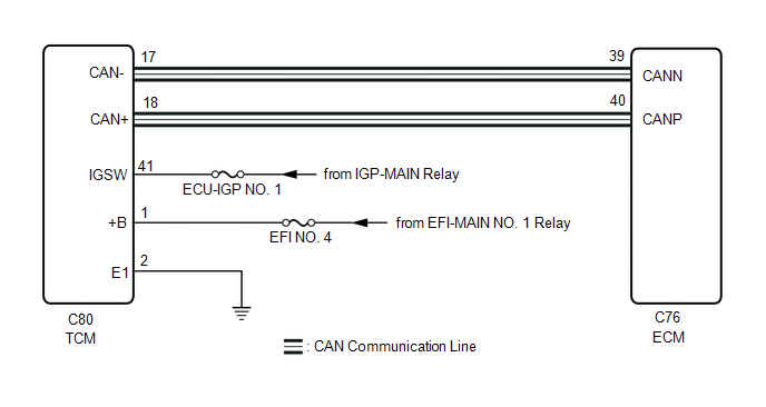
The Transmission Control Module (TCM) and ECM perform 2-way communication with each other via the Controller Area Network (CAN). The TCM sends signals to the ECM concerning required engine speed, required engine torque, warning indicators in the combination meter assembly, DTCs and other data. The ECM sends signals to the TCM concerning engine speed, opening angle of the throttle valve, temperature of intake air, temperature of engine coolant, engine torque and other data. If the TCM cannot communicate with the ECM, the TCM will conclude that there is a malfunction in the CAN communication system, illuminate the MIL and store this DTC.
|
DTC No. | Detection Item |
DTC Detection Condition | Trouble Area |
MIL | Note |
|---|---|---|---|---|---|
|
U010187 | Lost Communication with TCM Missing Message |
All of the following conditions are met for 1.25 seconds or more (1 trip detection logic):
|
| Comes on |
|
MONITOR STRATEGY
|
Related DTCs | U0101: Lost communication with TCM (verify communication) |
|
Required Sensors/Components (Main) | ECM |
|
Required Sensors/Components (Related) |
- |
| Frequency of Operation |
Continuous |
| Duration |
1.25 seconds |
| MIL Operation |
Immediate |
| Sequence of Operation |
None |
TYPICAL ENABLING CONDITIONS
|
Monitor runs whenever the following DTCs are not stored |
None |
| All of the following conditions are met |
- |
| Auxiliary battery voltage |
10 V or higher |
| Ignition switch |
ON |
| Starter |
Off |
TYPICAL MALFUNCTION THRESHOLDS
|
Communication signal | Lost communication with TCM |
CONFIRMATION DRIVING PATTERN
HINT:
- After repair has been completed, clear the DTC and then check that the vehicle has returned to normal by performing the following All Readiness check procedure.
Click here
.gif)
- When clearing the permanent DTCs, refer to the "CLEAR PERMANENT DTC" procedure.
Click here
- Connect the GTS to the DLC3.
- Turn the ignition switch to ON.
- Turn the GTS on.
- Clear the DTCs (even if no DTCs are stored, perform the clear DTC procedure).
- Turn the ignition switch off and wait for at least 30 seconds.
- Turn the ignition switch to ON.
- Turn the GTS on.
- Wait 5 seconds or more [A].
- Enter the following menus: Powertrain / Engine / Trouble Codes [B].
- Read the DTCs.
HINT:
- If a pending DTC is output, the system is malfunctioning.
- If a pending DTC is not output, perform the following procedure.
- Enter the following menus: Powertrain / Engine / Utility / All Readiness.
- Input the DTC: U010187.
- Check the DTC judgment result.
GTS Display
Description
NORMAL
- DTC judgment completed
- System normal
ABNORMAL
- DTC judgment completed
- System abnormal
INCOMPLETE
- DTC judgment not completed
- Perform driving pattern after confirming DTC enabling conditions
HINT:
- If the judgment result is NORMAL, the system is normal.
- If the judgment result is ABNORMAL, the system has a malfunction.
- If the judgment result is INCOMPLETE, perform steps [A] through [B] again.
- [A] to [B]: Normal judgment procedure.
The normal judgment procedure is used to complete DTC judgment and also used when clearing permanent DTCs.
- When clearing the permanent DTCs, do not disconnect the cable from the auxiliary battery terminal or attempt to clear the DTCs during this procedure, as doing so will clear the universal trip and normal judgment histories.
WIRING DIAGRAM
CAUTION / NOTICE / HINT
NOTICE:
Inspect the fuses for circuits related to this system before performing the following procedure.
HINT:
Read Freeze Frame Data using the GTS. The ECM records vehicle and driving condition information as Freeze Frame Data the moment a DTC is stored. When troubleshooting, Freeze Frame Data can help determine if the vehicle was moving or stationary, if the engine was warmed up or not, if the air fuel ratio was lean or rich, and other data from the time the malfunction occurred.
PROCEDURE
| 1. |
CHECK ANY OTHER DTCS OUTPUT (IN ADDITION TO DTC U010187) |
(a) Read the DTCs.
|
Result | Proceed to |
|---|---|
|
DTC U010187 is output |
A |
| DTC U010187 and other DTCs are output |
B |
HINT:
If any DTCs other than U010187 are output, troubleshoot those DTCs first.
| B |
.gif) | GO TO DTC CHART |
|
.gif)
| 2. |
CHECK TERMINAL VOLTAGE (POWER SOURCE OF TCM) |
|
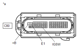
*a | Front view of wire harness connector (to TCM) |
(a) Disconnect the TCM connector.
(b) Turn the ignition switch to ON.
(c) Measure the voltage according to the value(s) in the table below.
Standard Voltage:
|
Tester Connection | Condition |
Specified Condition |
|---|---|---|
|
C80-1 (+B) - C80-2 (E1) |
Ignition switch ON | 11 to 14 V |
|
C80-41 (IGSW) - C80-2 (E1) |
Ignition switch ON | 11 to 14 V |
| NG | | GO TO TCM POWER SOURCE CIRCUIT for 2WD: Click here for AWD: Click here
|
|
| 3. |
CHECK HARNESS AND CONNECTOR (TCM - ECM) |
(a) Disconnect the TCM connector.
(b) Disconnect the ECM connector.
(c) Measure the resistance according to the value(s) in the table below.
Standard Resistance:
|
Tester Connection | Condition |
Specified Condition |
|---|---|---|
|
C80-18 (CAN+) - C76-40 (CANP) |
Always | Below 1 Ω |
|
C80-17 (CAN-) - C76-39 (CANN) |
Always | Below 1 Ω |
|
C80-18 (CAN+) or C76-40 (CANP) - Body ground and other terminals |
Always | 10 kΩ or higher |
|
C80-17 (CAN-) or C76-39 (CANN) - Body ground and other terminals |
Always | 10 kΩ or higher |
| NG | | REPAIR OR REPLACE HARNESS OR CONNECTOR |
|
| 4. |
REPLACE TCM |
for 2WD: Click here
for AWD: Click here
|
| 5. |
CLEAR DTC |
(a) Clear the DTCs.
Powertrain > Engine > Clear DTCs(b) Turn the ignition switch off and wait for at least 30 seconds.
|
| 6. |
CHECK WHETHER DTC OUTPUT RECURS (DTC U010187) |
(a) Drive the vehicle in accordance with the driving pattern described in the Confirmation Driving Pattern.
(b) Read the DTCs.
Powertrain > Engine > Trouble Codes|
Result | Proceed to |
|---|---|
|
DTCs are not output | A |
|
DTC U010187 is output |
B |
| A |
| END |
| B |
| REPLACE ECM
|


