Toyota Corolla Cross: Lost Communication with EMV Missing Message (B132187)
DESCRIPTION
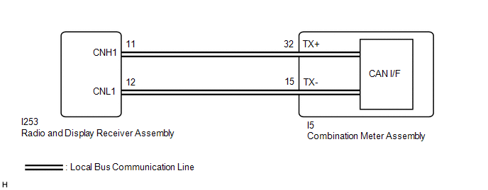
The combination meter assembly and radio and display receiver assembly communicate via local bus communication. This allows audio and visual system information to be displayed on the multi-information display.
This DTC is stored when a communication error occurs between the radio and display receiver assembly and combination meter assembly.
|
DTC No. | Detection Item |
DTC Detection Condition | Trouble Area |
|---|---|---|---|
|
B132187 | Lost Communication with EMV Missing Message | Diagnosis Condition:
|
|
WIRING DIAGRAM
CAUTION / NOTICE / HINT
NOTICE:
- When replacing the combination meter assembly, always replace it with a new one. If a combination meter assembly which was installed to another vehicle is used, the information stored in it will not match the information from the vehicle and a DTC may be stored.
- When replacing the combination meter assembly, update the ECU security key.
Click here
.gif)
- After the ignition switch is turned off, there may be a waiting time before disconnecting the negative (-) auxiliary battery terminal.
Click here
- If the power source circuit for any of the following ECUs is malfunctioning, DTCs may not be correctly output. Therefore, before performing troubleshooting using the following procedure, perform inspections related to the power source circuit of each ECU.
- Radio and display receiver assembly
Click here
- Combination meter assembly
Click here
- Radio and display receiver assembly
PROCEDURE
|
1. | CHECK FOR DTC |
(a) Check each system for DTCs.
Body Electrical > Combination Meter > Trouble Codes Body Electrical > Navigation System > Trouble Codes(b) Confirm the DTC combinations of the following table.
|
DTC Output Pattern |
DTC Output Part Name (Display on GTS) | |
|---|---|---|
|
Combination Meter Assembly (Combination Meter) |
Radio and Display Receiver Assembly (Audio AND Visual System) | |
|
1 | B132187 |
U11D087 |
| 2 |
B132187 | Not output |
|
Result | Proceed to |
|---|---|
|
DTC output pattern 1 |
A |
| DTC output pattern 2 |
B |
| B |
.gif) | GO TO STEP 3 |
|
.gif)
| 2. |
INSPECT EACH ECU (INTERNAL MALFUNCTION) |
(a) Remove 1 of the following ECUs.
- Radio and display receiver assembly
HINT:
Click here
- Combination meter assembly
HINT:
Click here
(b) Measure the resistance of the removed ECU.
NOTICE:
- Refer to the following table for the specified conditions of each ECU.
- If the specified conditions are met, repeat the inspection procedure from step (a) for another ECU.
HINT:
If the results of an ECU are not as specified, it is suspected that the ECU is the cause of the DTC.
| (1) Inspect the radio and display receiver assembly. Standard Resistance:
|
|
| (2) Inspect the combination meter assembly. Standard Resistance:
Result:
|
|
| A |
| REPAIR OR REPLACE HARNESS OR CONNECTOR |
| B |
| REPLACE RADIO AND DISPLAY RECEIVER ASSEMBLY |
| C |
| REPLACE COMBINATION METER ASSEMBLY |
| 3. |
CLEAR DTC |
(a) Clear the DTCs.
Body Electrical > Combination Meter > Clear DTCs
|
| 4. |
CHECK FOR DTC |
(a) Disconnect the cable from the negative (-) auxiliary battery terminal.
HINT:
By disconnecting the cable from the negative (-) auxiliary battery terminal, the internally stored information related to local bus communication for the combination meter assembly is reset.
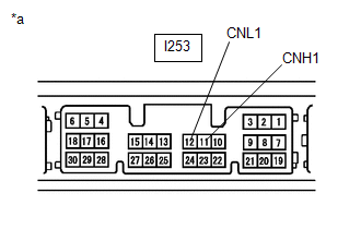
(b) Disconnect the I253 radio and display receiver assembly connector.
(c) Connect the cable to the negative (-) auxiliary battery terminal.
(d) Turn the ignition switch to ON.
(e) Wait 30 seconds or more.
(f) Check for DTCs.
Body Electrical > Combination Meter > Trouble CodesHINT:
By resetting the internally stored information related to local bus communication, the detection conditions of DTC B132187 are not met as the combination meter assembly does not detect the radio and display receiver assembly. If the combination meter assembly is operating normally, DTC B132187 will not be stored.
| Result |
Proceed to |
|---|---|
| DTC B132187 is not output |
A |
| DTC B132187 is output |
B |
| A |
| REPLACE RADIO AND DISPLAY RECEIVER ASSEMBLY |
| B |
| REPLACE COMBINATION METER ASSEMBLY |


