Toyota Corolla Cross: Fuel Sender Circuit Open (B150013,B150113)
DESCRIPTION
- The fuel sender gauge assembly is connected to the combination meter assembly via direct line. If there is an open or short in the direct line, the combination meter assembly stores DTC B150013.
- The fuel sender gauge assembly and No. 2 fuel sender gauge assembly are connected to the combination meter assembly via direct line. If there is an open or short in the direct line, the combination meter assembly stores DTC B150013 or B150113.*1
- *1: for AWD
|
DTC No. | Detection Item |
DTC Detection Condition | Trouble Area |
|---|---|---|---|
|
B150013 | Fuel Sender Circuit Open |
Diagnosis Condition:
Malfunction Status:
Malfunction Time:
|
|
| B150113 |
Sub Fuel Sender Circuit Open |
Diagnosis Condition:
Malfunction Status:
Malfunction Time:
|
|
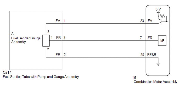
WIRING DIAGRAM
for 2WD with Gasoline Model

for HEV Model
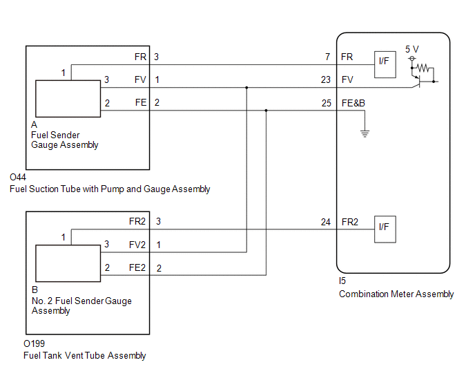
for AWD with Gasoline Model
CAUTION / NOTICE / HINT
NOTICE:
- When replacing the combination meter assembly, update the ECU security key.
Click here
.gif)
- When replacing the combination meter assembly, always replace it with a new one. If a combination meter assembly which was installed to another vehicle is used, the information stored in it will not match the information from the vehicle and a DTC may be stored.
PROCEDURE
|
1. | CHECK FOR DTC |
(a) Check for DTCs
Body Electrical > Combination Meter > Trouble Codes|
Result | Proceed to |
|---|---|
|
B150013 is output | A |
|
B150113 is output | B |
|
B150013 and B150113 are output |
C |
| B |
.gif) | GO TO STEP 10 |
| C |
| GO TO STEP 14 |
|
.gif)
| 2. |
READ VALUE USING GTS |
(a) Read the Data List according to the display on the GTS.
Body Electrical > Combination Meter > Data List|
Tester Display | Measurement Item |
Range | Normal Condition |
Diagnostic Note |
|---|---|---|---|---|
|
Fuel Input | Fuel input |
Min.: 0.00 L, Max.: 655.35 L or Unset |
Fuel sender input value |
- |
|
Tester Display |
|---|
| Fuel Input |
|
Result | Proceed to |
|---|---|
|
Fuel level data can be displayed on the GTS. |
A |
| Fuel level data cannot be displayed on the GTS |
B |
| A |
| REPLACE COMBINATION METER ASSEMBLY |
|
| 3. |
CONFIRM MODEL |
(a) Choose the model to be inspected.
|
Result | Proceed to |
|---|---|
|
for Gasoline Model | A |
|
for HEV Model | B |
| B |
| GO TO STEP 7 |
|
| 4. |
CHECK HARNESS AND CONNECTOR (FUEL SUCTION TUBE WITH PUMP AND GAUGE ASSEMBLY - COMBINATION METER ASSEMBLY) |
(a) Disconnect the O44 fuel suction tube with pump and gauge assembly connector.
(b) Disconnect the I5 combination meter assembly connector.
(c) Measure the resistance according to the value(s) in the table below.
Standard Resistance:
|
Tester Connection | Condition |
Specified Condition |
|---|---|---|
|
O44-1 (FV) - I5-23 (FV) |
Always | Below 1 Ω |
|
O44-3 (FR) - I5-7 (FR) |
Always | Below 1 Ω |
|
O44-2 (FE) - I5-25 (FE&B) |
Always | Below 1 Ω |
|
O44-1 (FV) or I5-23 (FV) - Body ground |
Always | 10 kΩ or higher |
|
O44-3 (FR) or I5-7 (FR) - Body ground |
Always | 10 kΩ or higher |
| NG | | REPAIR OR REPLACE HARNESS OR CONNECTOR |
|
| 5. |
INSPECT FUEL SENDER GAUGE ASSEMBLY |
- for 2WD:
Click here
- for AWD:
Click here
| NG | | REPLACE FUEL SENDER GAUGE ASSEMBLY for 2WD: Click here for AWD: Click here
|
|
| 6. |
INSPECT FUEL SUCTION TUBE WITH PUMP AND GAUGE ASSEMBLY |
(a) Measure the resistance according to the value(s) in the table below.
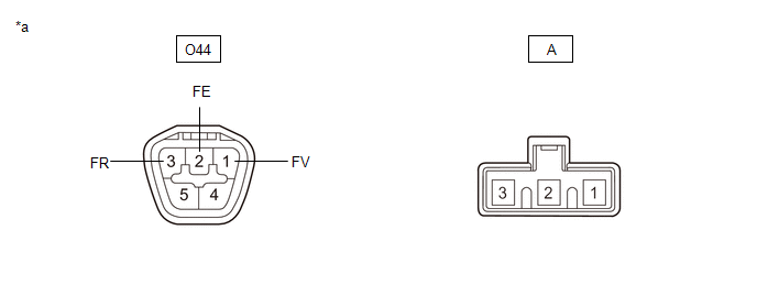
|
*a | Component without harness connected (Fuel Suction Tube with Pump and Gauge Assembly) |
- | - |
Standard Resistance:
|
Tester Connection | Condition |
Specified Condition |
|---|---|---|
|
O44-1 (FV) - A-3 | Always |
Below 1 Ω |
|
O44-2 (FE) - A-2 | Always |
Below 1 Ω |
|
O44-3 (FR) - A-1 | Always |
Below 1 Ω |
|
O44-1 (FV) - O44-3 (FR) or A-3 - A-1 |
Always | 10 kΩ or higher |
|
O44-1 (FV) - O44-2 (FE) or A-3 - A-2 |
Always | 10 kΩ or higher |
|
O44-2 (FE) - O44-3 (FR) or A-2 - A-1 |
Always | 10 kΩ or higher |
| OK | | REPLACE COMBINATION METER ASSEMBLY |
| NG | | REPLACE FUEL SUCTION TUBE WITH PUMP AND GAUGE ASSEMBLY for 2WD: Click here for AWD: Click here
|
| 7. |
CHECK HARNESS AND CONNECTOR (FUEL SUCTION TUBE WITH PUMP AND GAUGE ASSEMBLY - COMBINATION METER ASSEMBLY) |
(a) Disconnect the O217 fuel suction tube with pump and gauge assembly connector.
(b) Disconnect the I5 combination meter assembly connector.
(c) Measure the resistance according to the value(s) in the table below.
Standard Resistance:
|
Tester Connection | Condition |
Specified Condition |
|---|---|---|
|
O217-1 (FV) - I5-23 (FV) |
Always | Below 1 Ω |
|
O217-3 (FR) - I5-7 (FR) |
Always | Below 1 Ω |
|
O217-2 (FE) - I5-25 (FE&B) |
Always | Below 1 Ω |
|
O217-1 (FV) or I5-23 (FV) - Body ground |
Always | 10 kΩ or higher |
|
O217-3 (FR) or I5-7 (FR) - Body ground |
Always | 10 kΩ or higher |
| NG | | REPAIR OR REPLACE HARNESS OR CONNECTOR |
|
| 8. |
INSPECT FUEL SENDER GAUGE ASSEMBLY |
Click here
| NG | |
REPLACE FUEL SENDER GAUGE ASSEMBLY |
|
| 9. |
INSPECT FUEL SUCTION TUBE WITH PUMP AND GAUGE ASSEMBLY |
(a) Measure the resistance according to the value(s) in the table below.

|
*a | Component without harness connected (Fuel Suction Tube with Pump and Gauge Assembly) |
- | - |
Standard Resistance:
|
Tester Connection | Condition |
Specified Condition |
|---|---|---|
|
O217-1 (FV) - A-3 | Always |
Below 1 Ω |
|
O217-2 (FE) - A-2 | Always |
Below 1 Ω |
|
O217-3 (FR) - A-1 | Always |
Below 1 Ω |
|
O217-1 (FV) - O217-3 (FR) or A-3 - A-1 |
Always | 10 kΩ or higher |
|
O217-1 (FV) - O217-2 (FE) or A-3 - A-2 |
Always | 10 kΩ or higher |
|
O217-2 (FE) - O217-3 (FR) or A-2 - A-1 |
Always | 10 kΩ or higher |
| OK | | REPLACE COMBINATION METER ASSEMBLY |
| NG | | REPLACE FUEL SUCTION TUBE WITH PUMP AND GAUGE ASSEMBLY |
| 10. |
READ VALUE USING GTS |
(a) Read the Data List according to the display on the GTS.
Body Electrical > Combination Meter > Data List|
Tester Display | Measurement Item |
Range | Normal Condition |
Diagnostic Note |
|---|---|---|---|---|
|
Sub Fuel Input | Sub fuel input |
Min.: 0.00 L, Max.: 655.35 L or Unset |
Fuel sender input value |
- |
|
Tester Display |
|---|
| Sub Fuel Input |
|
Result | Proceed to |
|---|---|
|
Fuel level data can be displayed on the GTS. |
A |
| Fuel level data cannot be displayed on the GTS |
B |
| A |
| REPLACE COMBINATION METER ASSEMBLY |
|
| 11. |
CHECK HARNESS AND CONNECTOR (FUEL TANK VENT TUBE ASSEMBLY - COMBINATION METER ASSEMBLY) |
(a) Disconnect the O199 fuel tank vent tube assembly connector.
(b) Disconnect the I5 combination meter assembly connector.
(c) Measure the resistance according to the value(s) in the table below.
Standard Resistance:
|
Tester Connection | Condition |
Specified Condition |
|---|---|---|
|
O199-3 (FR2) - I5-24 (FR2) |
Always | Below 1 Ω |
|
O199-1 (FV2) - I5-23 (FV) |
Always | Below 1 Ω |
|
O199-2 (FE2) - I5-25 (FE&B) |
Always | Below 1 Ω |
|
O199-3 (FR2) or I5-24 (FR2)- Body ground |
Always | 10 kΩ or higher |
| NG | | REPAIR OR REPLACE HARNESS OR CONNECTOR |
|
| 12. |
INSPECT NO. 2 FUEL SENDER GAUGE ASSEMBLY |
Click here
| NG | | REPLACE NO. 2 FUEL SENDER GAUGE ASSEMBLY |
|
| 13. |
INSPECT FUEL TANK VENT TUBE ASSEMBLY |
(a) Measure the resistance according to the value(s) in the table below.
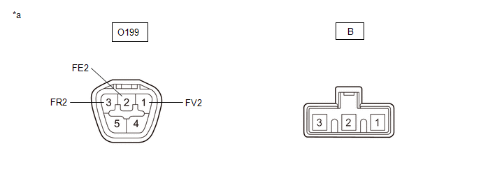
|
*a | Component without harness connected (Fuel Tank Vent Tube Assembly) |
- | - |
Standard Resistance:
|
Tester Connection | Condition |
Specified Condition |
|---|---|---|
|
O199-1 (FV2) - B-3 | Always |
Below 1 Ω |
|
O199-2 (FE2) - B-2 | Always |
Below 1 Ω |
|
O199-3 (FR2) - B-1 | Always |
Below 1 Ω |
|
O199-1 (FV2) - O199-2 (FE2) or B-3 - B-2 |
Always | 10 kΩ or higher |
|
O199-1 (FV2) - O199-3 (FR2) or B-3 - B-1 |
Always | 10 kΩ or higher |
|
O199-2 (FE2) - O199-3 (FR2) or B-2 - B-1 |
Always | 10 kΩ or higher |
| OK | | REPLACE COMBINATION METER ASSEMBLY |
| NG | | REPLACE FUEL TANK VENT TUBE ASSEMBLY |
| 14. |
READ VALUE USING GTS |
(a) Read the Data List according to the display on the GTS.
Body Electrical > Combination Meter > Data List|
Tester Display | Measurement Item |
Range | Normal Condition |
Diagnostic Note |
|---|---|---|---|---|
|
Fuel Input | Fuel input |
Min.: 0.00 L, Max.: 655.35 L or Unset |
Fuel sender input value |
- |
| Sub Fuel Input |
Sub fuel input | Min.: 0.00 L, Max.: 655.35 L or Unset |
Fuel sender input value |
- |
|
Tester Display |
|---|
| Fuel Input |
|
Sub Fuel Input |
|
Result | Proceed to |
|---|---|
|
Fuel level data can be displayed on the GTS. |
A |
| Fuel level data cannot be displayed on the GTS |
B |
| A |
| REPLACE COMBINATION METER ASSEMBLY |
|
| 15. |
CHECK HARNESS AND CONNECTOR (FUEL SUCTION TUBE WITH PUMP AND GAUGE ASSEMBLY AND FUEL TANK VENT TUBE ASSEMBLY - COMBINATION METER ASSEMBLY) |
(a) Disconnect the O44 fuel suction tube with pump and gauge assembly connector.
(b) Disconnect the O199 fuel tank vent tube assembly connector.
(c) Disconnect the I5 combination meter assembly connector.
(d) Measure the resistance according to the value(s) in the table below.
Standard Resistance:
|
Tester Connection | Condition |
Specified Condition |
|---|---|---|
|
O44-1 (FV) - I5-23 (FV) |
Always | Below 1 Ω |
|
O44-2 (FE) - I5-25 (FE&B) |
Always | Below 1 Ω |
|
O199-1 (FV2) - I5-23 (FV) |
Always | Below 1 Ω |
|
O199-2 (FE2) - I5-25 (FE&B) |
Always | Below 1 Ω |
|
O44-1 (FV), O199-1 (FV2) or I5-23 (FV)- Body ground |
Always | 10 kΩ or higher |
| OK | | REPLACE COMBINATION METER ASSEMBLY |
| NG | | REPAIR OR REPLACE HARNESS OR CONNECTOR |


