Toyota Corolla Cross: Turn Signal/Hazard Flasher Circuit Current Above Threshold (B150819)
DESCRIPTION
This DTC is stored when the combination meter assembly detects a short in a turn signal light circuit.
HINT:
If there is a short in a turn signal light circuit, all of the turn signal lights in that circuit will not blink.
|
DTC No. | Detection Item |
DTC Detection Condition | Trouble Area |
|---|---|---|---|
|
B150819 | Turn Signal/Hazard Flasher Circuit Current Above Threshold |
Diagnosis Condition:
Malfunction Status:
|
|
- *1: for Bulb Type Clearance Light
- *2: w/ Side Turn Signal Light
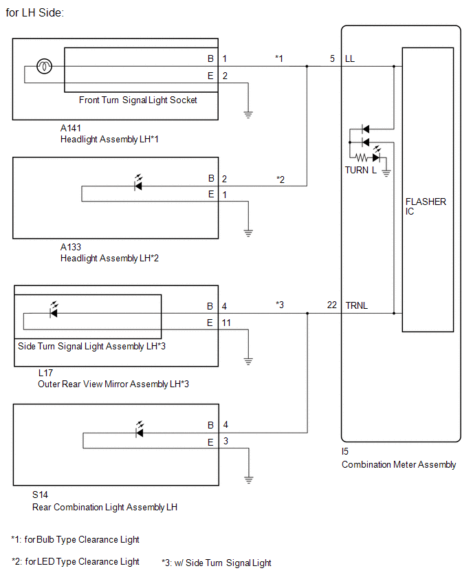
WIRING DIAGRAM
CAUTION / NOTICE / HINT
NOTICE:
- When replacing the combination meter assembly, always replace it with a new one. If a combination meter assembly which was installed to another vehicle is used, the information stored in it will not match the information from the vehicle and a DTC may be stored.
- Inspect the turn signal light bulbs before performing the following procedure.
- When replacing the combination meter assembly, update the ECU security key
Click here
.gif)
PROCEDURE
|
1. | CHECK SYMPTOMS |
(a) Check the problem symptoms.
|
Result | Proceed to |
|---|---|
|
All LH side turn signal lights do not blink |
A |
| All RH side turn signal lights do not blink |
B |
| B |
.gif) | GO TO STEP 12 |
|
.gif)
| 2. |
CONFIRM MODEL |
(a) Choose the model to be inspected.
|
Result | Proceed to |
|---|---|
|
for Bulb Type Clearance Light |
A |
| for LED Type Clearance Light |
B |
| B |
| GO TO STEP 4 |
|
| 3. |
CHECK LH SIDE TURN SIGNAL LIGHTS (FRONT TURN SIGNAL LIGHT CIRCUIT) |
(a) Disconnect the A141 headlight assembly LH connector.
(b) Operate the turn signal switch and check that the LH side turn signal lights other than the front turn signal light blink.
HINT:
If the LH side turn signal lights other than the front turn signal light blink, the front turn signal light socket is malfunctioning.
|
Result | Proceed to |
|---|---|
|
LH side turn signal lights other than the front turn signal light blink |
A |
| Problem symptoms do not change (All LH side turn signal lights do not blink) |
B |
| A |
| REPLACE FRONT TURN SIGNAL LIGHT SOCKET |
| B |
| GO TO STEP 5 |
| 4. |
CHECK LH SIDE TURN SIGNAL LIGHTS (FRONT TURN SIGNAL LIGHT CIRCUIT) |
(a) Disconnect the A133 headlight assembly LH connector.
(b) Operate the turn signal switch and check that the LH side turn signal lights other than the front turn signal light blink.
HINT:
If the LH side turn signal lights other than the front turn signal light blink, the headlight front turn signal LED is malfunctioning.
|
Result | Proceed to |
|---|---|
|
LH side turn signal lights other than the front turn signal light blink |
A |
| Problem symptoms do not change (All LH side turn signal lights do not blink) |
B |
| A |
| REPLACE HEADLIGHT ASSEMBLY LH |
|
| 5. |
CONFIRM MODEL |
(a) Choose the model to be inspected.
|
Result | Proceed to |
|---|---|
|
w/o Side Turn Signal Light |
A |
| w/ Side Turn Signal Light |
B |
| B |
| GO TO STEP 8 |
|
| 6. |
CHECK LH SIDE TURN SIGNAL LIGHTS (REAR TURN SIGNAL LIGHT CIRCUIT) |
(a) Connect the headlight assembly LH connector.
(b) Disconnect the S14 rear combination light assembly LH connector.
(c) Operate the turn signal switch and check that the LH rear turn signal lights other than the rear turn signal light blink.
HINT:
If the LH side turn signal lights other than the rear turn signal light blink, the rear combination light assembly LH is malfunctioning.
|
Result | Proceed to |
|---|---|
|
LH rear turn signal lights other than the rear turn signal light blink |
A |
| Problem symptoms do not change (All LH side turn signal lights do not blink) |
B |
| A |
| REPLACE REAR COMBINATION LIGHT ASSEMBLY LH |
|
| 7. |
CHECK HARNESS AND CONNECTOR (LH SIDE EACH PARTS - COMBINATION METER ASSEMBLY) |
(a) Disconnect the A141*1 or A133*2 headlight assembly LH connector.
- *1: for Bulb Type Clearance Light
- *2: for LED Type Clearance Light
(b) Disconnect the I5 combination meter assembly connector.
(c) Measure the resistance according to the value(s) in the table below.
Standard Resistance:
|
Tester Connection | Condition |
Specified Condition |
|---|---|---|
|
A141-1 (B) or I5-5 (LL) - Body ground*1 |
Always | 10 kΩ or higher |
|
A133-2 (B) or I5-5 (LL) - Body ground*2 |
Always | 10 kΩ or higher |
|
S14-4 (B) or I5-22 (TRNL) - Body ground |
Always | 10 kΩ or higher |
- *1: for Bulb Type Clearance Light
- *2: for LED Type Clearance Light
| OK | | REPLACE COMBINATION METER ASSEMBLY |
| NG | | REPAIR OR REPLACE HARNESS OR CONNECTOR |
| 8. |
CHECK LH SIDE TURN SIGNAL LIGHTS (REAR TURN SIGNAL LIGHT CIRCUIT) |
(a) Connect the headlight assembly LH connector.
(b) Disconnect the L17 outer rear view mirror assembly LH connector.
(c) Operate the turn signal switch and check that the LH side turn signal lights other than the side turn signal light blink.
HINT:
If the LH side turn signal lights other than the side turn signal light blink, a component of the outer rear view mirror assembly LH is malfunctioning.
|
Result | Proceed to |
|---|---|
|
LH side turn signal lights other than the side turn signal light blink |
A |
| Problem symptoms do not change (All LH side turn signal lights do not blink) |
B |
| B |
| GO TO STEP 10 |
|
| 9. |
CHECK LH SIDE TURN SIGNAL LIGHTS (OUTER REAR VIEW MIRROR ASSEMBLY LH) |
(a) Remove the side turn signal light assembly LH from outer rear view mirror assembly LH.
Click here
(b) Connect the wire harness connector to the outer rear view mirror assembly LH connector.
(c) Operate the turn signal switch and check that the LH side turn signal lights other than the side turn signal light blink.
HINT:
If all LH side turn signal lights do not blink, the outer rear view mirror assembly LH is malfunctioning.
|
Result | Proceed to |
|---|---|
|
LH side turn signal lights other than the side turn signal light blink |
A |
| All LH side turn signal lights do not blink |
B |
| A |
| REPLACE SIDE TURN SIGNAL LIGHT ASSEMBLY LH |
| B |
| REPLACE OUTER REAR VIEW MIRROR ASSEMBLY LH |
| 10. |
CHECK LH SIDE TURN SIGNAL LIGHTS (REAR TURN SIGNAL LIGHT CIRCUIT) |
(a) Connect the outer rear view mirror assembly LH connector.
(b) Disconnect the S14 rear combination light assembly LH connector.
(c) Operate the turn signal switch and check that the LH rear turn signal lights other than the rear turn signal light blink.
HINT:
If the LH side turn signal lights other than the rear turn signal light blink, the rear combination light assembly LH is malfunctioning.
|
Result | Proceed to |
|---|---|
|
LH rear turn signal lights other than the rear turn signal light blink |
A |
| Problem symptoms do not change (All LH side turn signal lights do not blink) |
B |
| A |
| REPLACE REAR COMBINATION LIGHT ASSEMBLY LH |
|
| 11. |
CHECK HARNESS AND CONNECTOR (LH SIDE EACH PARTS - COMBINATION METER ASSEMBLY) |
(a) Disconnect the A141*1 or A133*2 headlight assembly LH connector.
- *1: for Bulb Type Clearance Light
- *2: for LED Type Clearance Light
(b) Disconnect the L17 outer rear view mirror assembly LH connector.
(c) Disconnect the I5 combination meter assembly connector.
(d) Measure the resistance according to the value(s) in the table below.
Standard Resistance:
|
Tester Connection | Condition |
Specified Condition |
|---|---|---|
|
A141-1 (B) or I5-5 (LL) - Body ground*1 |
Always | 10 kΩ or higher |
|
A133-2 (B) or I5-5 (LL) - Body ground*2 |
Always | 10 kΩ or higher |
|
L17-4 (B), S14-4 (B) or I5-22 (TRNL) - Body ground |
Always | 10 kΩ or higher |
- *1: for Bulb Type Clearance Light
- *2: for LED Type Clearance Light
| OK | | REPLACE COMBINATION METER ASSEMBLY |
| NG | | REPAIR OR REPLACE HARNESS OR CONNECTOR |
| 12. |
CONFIRM MODEL |
(a) Choose the model to be inspected.
|
Result | Proceed to |
|---|---|
|
for Bulb Type Clearance Light |
A |
| for LED Type Clearance Light |
B |
| B |
| GO TO STEP 14 |
|
| 13. |
CHECK RH SIDE TURN SIGNAL LIGHTS (FRONT TURN SIGNAL LIGHT CIRCUIT) |
(a) Disconnect the A146 headlight assembly RH connector.
(b) Operate the turn signal switch and check that the RH side turn signal lights other than the front turn signal light blink.
HINT:
If the RH side turn signal lights other than the front turn signal light blink, the front turn signal light socket is malfunctioning.
|
Result | Proceed to |
|---|---|
|
RH side turn signal lights other than the front turn signal light blink |
A |
| Problem symptoms do not change (All RH side turn signal lights do not blink) |
B |
| A |
| REPLACE FRONT TURN SIGNAL LIGHT SOCKET |
| B |
| GO TO STEP 15 |
| 14. |
CHECK RH SIDE TURN SIGNAL LIGHTS (FRONT TURN SIGNAL LIGHT CIRCUIT) |
(a) Disconnect the A136 headlight assembly RH connector.
(b) Operate the turn signal switch and check that the RH side turn signal lights other than the front turn signal light blink.
HINT:
If the RH side turn signal lights other than the front turn signal light blink, the headlight front turn signal LED is malfunctioning.
|
Result | Proceed to |
|---|---|
|
RH side turn signal lights other than the front turn signal light blink |
A |
| Problem symptoms do not change (All RH side turn signal lights do not blink) |
B |
| A |
| REPLACE HEADLIGHT ASSEMBLY RH |
|
| 15. |
CONFIRM MODEL |
(a) Choose the model to be inspected.
|
Result | Proceed to |
|---|---|
|
w/o Side Turn Signal Light |
A |
| w/ Side Turn Signal Light |
B |
| B |
| GO TO STEP 18 |
|
| 16. |
CHECK RH SIDE TURN SIGNAL LIGHTS (REAR TURN SIGNAL LIGHT CIRCUIT) |
(a) Connect the headlight assembly RH connector.
(b) Disconnect the S15 rear combination light assembly RH connector.
(c) Operate the turn signal switch and check that the RH rear turn signal lights other than the rear turn signal light blink.
HINT:
If the RH side turn signal lights other than the rear turn signal light blink, the rear combination light assembly RH is malfunctioning.
|
Result | Proceed to |
|---|---|
|
RH rear turn signal lights other than the rear turn signal light blink |
A |
| Problem symptoms do not change (All RH side turn signal lights do not blink) |
B |
| A |
| REPLACE REAR COMBINATION LIGHT ASSEMBLY RH |
|
| 17. |
CHECK HARNESS AND CONNECTOR (RH SIDE EACH PARTS - COMBINATION METER ASSEMBLY) |
(a) Disconnect the A146*1 or A136*2 headlight assembly RH connector.
- *1: for Bulb Type Clearance Light
- *2: for LED Type Clearance Light
(b) Disconnect the I5 combination meter assembly connector.
(c) Measure the resistance according to the value(s) in the table below.
Standard Resistance:
|
Tester Connection | Condition |
Specified Condition |
|---|---|---|
|
A146-1 (B) or I5-6 (LR) - Body ground*1 |
Always | 10 kΩ or higher |
|
A136-2 (B) or I5-6 (LR) - Body ground*2 |
Always | 10 kΩ or higher |
|
S15-4 (B) or I5-21 (TRNR) - Body ground |
Always | 10 kΩ or higher |
- *1: for Bulb Type Clearance Light
- *2: for LED Type Clearance Light
| OK | | REPLACE COMBINATION METER ASSEMBLY |
| NG | | REPAIR OR REPLACE HARNESS OR CONNECTOR |
| 18. |
CHECK RH SIDE TURN SIGNAL LIGHTS (SIDE TURN SIGNAL LIGHT CIRCUIT) |
(a) Connect the headlight assembly RH connector.
(b) Disconnect the K17 outer rear view mirror assembly RH connector.
(c) Operate the turn signal switch and check that the RH side turn signal lights other than the side turn signal light blink.
HINT:
If the RH side turn signal lights other than the side turn signal light blink, a component of the outer rear view mirror assembly RH is malfunctioning.
|
Result | Proceed to |
|---|---|
|
RH side turn signal lights other than the side turn signal light blink |
A |
| Problem symptoms do not change (All RH side turn signal lights do not blink) |
B |
| B |
| GO TO STEP 20 |
|
| 19. |
CHECK RH SIDE TURN SIGNAL LIGHTS (OUTER REAR VIEW MIRROR ASSEMBLY RH) |
(a) Remove the side turn signal light assembly RH from outer rear view mirror assembly RH.
Click here
(b) Connect the wire harness connector to the outer rear view mirror assembly RH connector.
(c) Operate the turn signal switch and check that the RH side turn signal lights other than the side turn signal light blink.
HINT:
If all RH side turn signal lights do not blink, the outer rear view mirror assembly RH is malfunctioning.
|
Result | Proceed to |
|---|---|
|
RH side turn signal lights other than the side turn signal light blink |
A |
| All RH side turn signal lights do not blink |
B |
| A |
| REPLACE SIDE TURN SIGNAL LIGHT ASSEMBLY RH |
| B |
| REPLACE OUTER REAR VIEW MIRROR ASSEMBLY RH |
| 20. |
CHECK RH SIDE TURN SIGNAL LIGHTS (REAR TURN SIGNAL LIGHT CIRCUIT) |
(a) Connect the outer rear view mirror assembly RH connector.
(b) Disconnect the S15 rear combination light assembly RH connector.
(c) Operate the turn signal switch and check that the RH rear turn signal lights other than the rear turn signal light blink.
HINT:
If the RH side turn signal lights other than the rear turn signal light blink, the rear combination light assembly RH is malfunctioning.
|
Result | Proceed to |
|---|---|
|
RH side turn signal lights other than the rear turn signal light blink |
A |
| Problem symptoms do not change (All RH side turn signal lights do not blink) |
B |
| A |
| REPLACE REAR COMBINATION LIGHT ASSEMBLY RH |
|
| 21. |
CHECK HARNESS AND CONNECTOR (RH SIDE EACH PARTS - COMBINATION METER ASSEMBLY) |
(a) Disconnect the A146*1 or A136*2 headlight assembly RH connector.
- *1: for Bulb Type Clearance Light
- *2: for LED Type Clearance Light
(b) Disconnect the K17 outer rear view mirror assembly RH connector.
(c) Disconnect the I5 combination meter assembly connector.
(d) Measure the resistance according to the value(s) in the table below.
Standard Resistance:
|
Tester Connection | Condition |
Specified Condition |
|---|---|---|
|
A146-1 (B) or I5-6 (LR) - Body ground*1 |
Always | 10 kΩ or higher |
|
A136-2 (B) or I5-6 (LR) - Body ground*2 |
Always | 10 kΩ or higher |
|
K17-4 (B), S15-4 (B) or I5-21 (TRNR) - Body ground |
Always | 10 kΩ or higher |
- *1: for Bulb Type Clearance Light
- *2: for LED Type Clearance Light
| OK | | REPLACE COMBINATION METER ASSEMBLY |
| NG | | REPAIR OR REPLACE HARNESS OR CONNECTOR |

