Toyota Corolla Cross: Inspection
INSPECTION
PROCEDURE
1. INSPECT PRELOAD
|
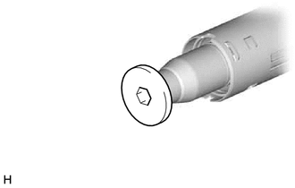
(a) Using a 10 mm hexagon socket wrench, install the steering wheel assembly
set bolt to the steering main shaft.
NOTICE:
- Do not apply excessive torque to the steering wheel assembly set
bolt by using a tool such as an impact wrench.
- The steering wheel assembly set bolt is used for turning the steering
main shaft during inspection of the steering main shaft rotating torque.
- Remove the steering wheel assembly set bolt after performing this
inspection.
|
|
|
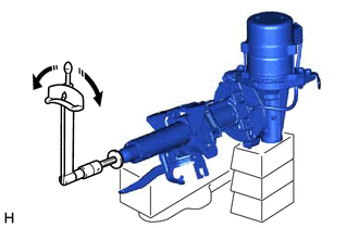
(b) Secure the steering column assembly in a vise using aluminum plates,
cloths and wooden blocks.
NOTICE:
- Do not overtighten the vise, as the steering column assembly may
become deformed.
- Support the steering column assembly with wooden blocks or similar
items to ensure that it does not fall.
|
|
(c) Using a torque wrench, turn the steering main shaft at a constant rate of
approximately 1 revolution every 4 seconds and measure the preload.
Preload:
1.1 to 2.3 N*m (12 to 23 kgf*cm, 10 to 20 in.*lbf)
.png) |
Turn
|
(d) If the preload is not as specified, replace the power steering ECU assembly
or electric power steering column sub-assembly with a new one.
(e) Remove the steering wheel assembly set bolt.
2. INSPECT STEERING COLUMN ASSEMBLY
|
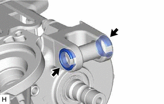
(a) Check that the 2 bushings are securely installed to the steering
column assembly.
|
|
(b) If the bushings are deformed, missing or damaged, replace the electric power
steering column sub-assembly with a new one.
READ NEXT:
REASSEMBLY
CAUTION / NOTICE / HINT
COMPONENTS (REASSEMBLY)
Procedure
Part Name Code
1
IGNITION OR STARTER SWITCH ASSEMB
INSTALLATION
CAUTION / NOTICE / HINT
COMPONENTS (INSTALLATION)
Procedure
Part Name Code
1
ALIGN FRONT WHEELS FACING STR
Removal
REMOVAL
CAUTION / NOTICE / HINT
COMPONENTS (REMOVAL)
Procedure
Part Name Code
1
SWITCH BASE
55449
SEE MORE:
DIAGNOSIS SYSTEM
CHECK WARNING LIGHT
NOTICE:
When there is a problem with the tire pressure warning system, the tire
pressure warning light blinks at 0.5 second intervals, and illuminates after
1 minute.
When the malfunction has been corrected, the tire pressure warning light
goes
REMOVAL CAUTION / NOTICE / HINT COMPONENTS (REMOVAL)
Procedure Part Name Code
1 DRAIN ENGINE COOLANT
- -
- 2
INVERTER WITH CONVERTER ASSEMBLY
G92A0 -
- -
3 NO. 3 WATER BY-PASS HOSE
16267 -