Toyota Corolla Cross: Installation
INSTALLATION
CAUTION / NOTICE / HINT
COMPONENTS (INSTALLATION)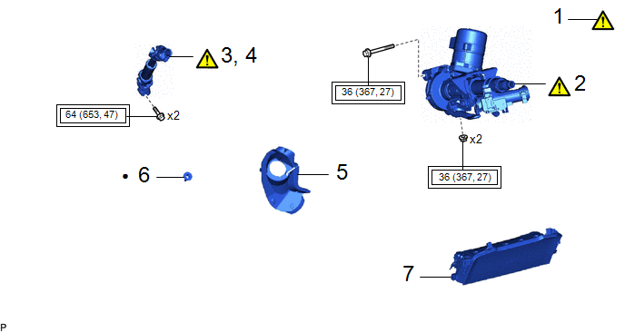
|
Procedure |
Part Name Code |
.png) |
.png) |
.png) |
|
|---|---|---|---|---|---|
|
1 |
ALIGN FRONT WHEELS FACING STRAIGHT AHEAD |
- |
|
- |
- |
|
2 |
STEERING COLUMN ASSEMBLY |
- |
|
- |
- |
|
3 |
INSTALL NO. 2 STEERING INTERMEDIATE SHAFT ASSEMBLY |
45260 |
|
- |
- |
|
4 |
CONNECT NO. 2 STEERING INTERMEDIATE SHAFT ASSEMBLY |
45260 |
|
- |
- |
|
5 |
COLUMN HOLE COVER SILENCER SHEET |
45259A |
- |
- |
- |
|
6 |
STOP LIGHT SWITCH MOUNTING ADJUSTER |
84345 |
- |
- |
- |
|
7 |
LOWER NO. 1 INSTRUMENT PANEL AIRBAG ASSEMBLY |
73900 |
- |
- |
- |
 |
Tightening torque for "Major areas involving basic vehicle performance such as moving/turning/stopping" : N*m (kgf*cm, ft.*lbf) |
● |
Non-reusable part |
|
Procedure |
Part Name Code |
|
|
|
|
|---|---|---|---|---|---|
|
8 |
TURN SIGNAL SWITCH ASSEMBLY WITH SPIRAL CABLE SUB-ASSEMBLY |
- |
|
- |
- |
|
9 |
TRANSPONDER KEY COIL |
89782 |
- |
- |
- |
|
10 |
UPPER STEERING COLUMN COVER |
45286B |
- |
- |
- |
|
11 |
LOWER STEERING COLUMN COVER |
45287 |
- |
- |
- |
|
12 |
STEERING WHEEL ASSEMBLY |
45100 |
- |
- |
- |
|
13 |
PERFORM POWER STEERING ECU INITIAL SETTING (TORQUE SENSOR ZERO POINT CALIBRATION AND ASSIST MAP WRITING) |
- |
- |
- |
|
|
14 |
PERFORM END POSITION INITIAL SETTING |
- |
- |
- |
|
|
15 |
PERFORM CALIBRATION |
- |
- |
- |
|
|
*A |
w/ Parking Assist Monitor System |
*B |
w/o Smart Key System |
|
|
Tightening torque for "Major areas involving basic vehicle performance such as moving/turning/stopping" : N*m (kgf*cm, ft.*lbf) |
- |
- |
PROCEDURE
1. ALIGN FRONT WHEELS FACING STRAIGHT AHEAD
|
|
Click here |
2. INSTALL STEERING COLUMN ASSEMBLY
|
|
NOTICE:
|
Torque:
36 N·m {367 kgf·cm, 27 ft·lbf}
3. INSTALL NO. 2 STEERING INTERMEDIATE SHAFT ASSEMBLY

|
*a |
Matchmark |
- |
- |
(1) Align the matchmarks on the No. 2 steering intermediate shaft assembly and steering column assembly.
(2) Connect the No. 2 steering intermediate shaft assembly to the steering column assembly with the bolt.
Torque:
64 N·m {653 kgf·cm, 47 ft·lbf}
4. CONNECT NO. 2 STEERING INTERMEDIATE SHAFT ASSEMBLY

|
*a |
Matchmark |
- |
- |
(1) Align the matchmarks on the No. 2 steering intermediate shaft assembly and steering gear assembly.
(2) Connect the No. 2 steering intermediate shaft assembly to the steering gear assembly with the bolt.
Torque:
64 N·m {653 kgf·cm, 47 ft·lbf}
5. INSTALL COLUMN HOLE COVER SILENCER SHEET
6. INSTALL STOP LIGHT SWITCH MOUNTING ADJUSTER
Click here .gif)
7. INSTALL LOWER NO. 1 INSTRUMENT PANEL AIRBAG ASSEMBLY
Click here
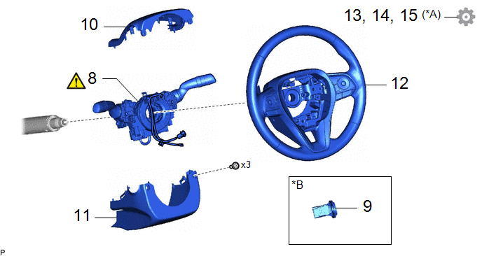
8. INSTALL TURN SIGNAL SWITCH ASSEMBLY WITH SPIRAL CABLE SUB-ASSEMBLY
|
|
NOTICE:
|
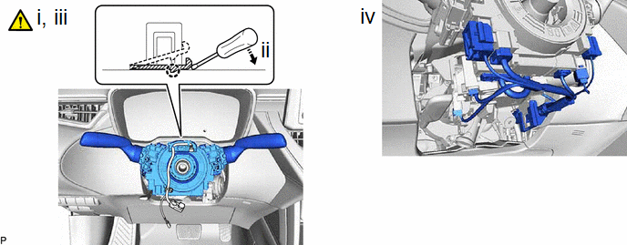
|
*a |
Clamp |
- |
- |
.png) |
Install in this Direction |
- |
- |
(1) Using pliers, expand the clamp.
(2) While holding the clamp expanded, install the turn signal switch assembly with spiral cable sub-assembly to the steering column assembly and engage the claw.
(3) Return the clamp to its original position.
(4) Connect each connector.
HINT:
As the illustration shown is an example, the actual details may differ.
9. INSTALL TRANSPONDER KEY COIL (w/o Smart Key System)
10. INSTALL UPPER STEERING COLUMN COVER
11. INSTALL LOWER STEERING COLUMN COVER
12. INSTALL STEERING WHEEL ASSEMBLY
Click here
13. PERFORM POWER STEERING ECU INITIAL SETTING (TORQUE SENSOR ZERO POINT CALIBRATION AND ASSIST MAP WRITING)
Click here
14. PERFORM END POSITION INITIAL SETTING
Click here
15. PERFORM CALIBRATION (w/ Parking Assist Monitor System)
Click here


