Toyota Corolla Cross Owners & Service Manuals

Toyota Corolla Cross: Steering Heater Switch

Removal

REMOVAL

CAUTION / NOTICE / HINT

COMPONENTS (REMOVAL)
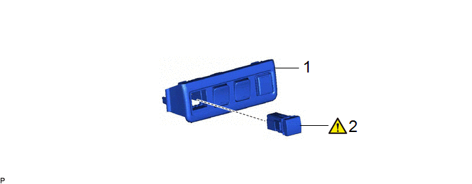
Procedure

Part Name Code

1

SWITCH BASE

55449D

-

-

-

2

STEERING HEATER SWITCH

84255

-

-

PROCEDURE

1. REMOVE SWITCH BASE

HINT:

As the illustration shown is an example, the actual details may differ.

2. REMOVE STEERING HEATER SWITCH

(1) Using a screwdriver with its tip wrapped with protective tape, disengage the 2 claws and remove the steering heater switch.

Inspection

INSPECTION

PROCEDURE

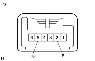
1. INSPECT STEERING HEATER SWITCH

(a) Check the resistance.

(1) Measure the resistance according to the value(s) in the table below.

Standard Resistance:

Tester Connection

Condition

Specified Condition

5 (IG) - 2 (B)

Steering heater switch is pushed

Below 1 Ω

5 (IG) - 2 (B)

Steering heater switch is not pushed

10 kΩ or higher

(2) If the result is not as specified, replace the steering heater switch.

*a

Component without harness connected

(Steering Heater Switch)

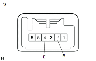
(b) Check the indicator.

(1) Apply auxiliary battery voltage to the steering heater switch and check that the indicator illuminates.

OK:

Tester Connection

Condition

Specified Condition

2 (B) - 4 (E)

2 (B) → Auxiliary battery positive (+)

4 (E) → Auxiliary battery negative (-)

Indicator illuminates

*a

Component without harness connected

(Steering Heater Switch)

(2) If the result is not as specified, replace the steering heater switch.

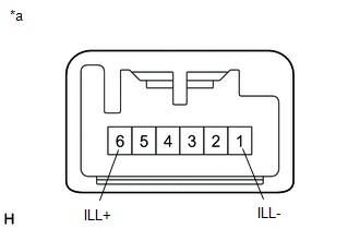
(c) Check the illumination.

(1) Apply auxiliary battery voltage to the steering heater switch and check that the illumination.

OK:

Tester Connection

Condition

Specified Condition

6 (ILL+) - 1 (ILL-)

6 (ILL+) → Auxiliary battery positive (+)

1 (ILL-) → Auxiliary battery negative (-)

Illumination illuminates

*a

Component without harness connected

(Steering Heater Switch)

(2) If the result is not as specified, replace the steering heater switch.

Installation

INSTALLATION

CAUTION / NOTICE / HINT

COMPONENTS (INSTALLATION)
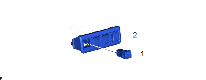
Procedure

Part Name Code

1

STEERING HEATER SWITCH

84255

-

-

-

2

SWITCH BASE

55449D

-

-

-

PROCEDURE

1. INSTALL STEERING HEATER SWITCH

2. INSTALL SWITCH BASE

    READ NEXT:

     Steering Pad Switch

     Removal

    REMOVAL CAUTION / NOTICE / HINT COMPONENTS (REMOVAL) Procedure Part Name Code 1 HORN BUTTON ASSEMBLY 45130

     Inspection

    INSPECTION PROCEDURE 1. INSPECT STEERING PAD SWITCH ASSEMBLY (a) Measure the resistance according to the value(s) in the table below. *a Component without harness connected

    SEE MORE:

     Shut Down Signal Circuit

    DESCRIPTION The cause of the malfunction may be a shutdown signal. Check whether there is a shutdown signal +B short circuit. Related Parts Check Area Inspection HSDN terminal Check that the HSDN terminal voltage decreases to check for an open or short circuit while READY off

     Starter Relay Circuit Short to Ground (P061511)

    DESCRIPTION When the engine is started by stop and start control, the engine stop and start ECU controls the starter assembly by activating the ST NO. 1 relay via voltage from terminal STA. If overcurrent is detected in the starter relay circuit, the engine stop and start ECU stores DTC P061511.

    © 2020-2024 Copyright www.tcorollacross.com