Toyota Corolla Cross: Inspection
INSPECTION
PROCEDURE
1. INSPECT WATER INLET WITH THERMOSTAT SUB-ASSEMBLY
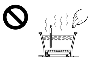
CAUTION:
- Do not put your hands into the water that has been heated for the inspection.
- Touching the heated water could result in burns.

HINT:
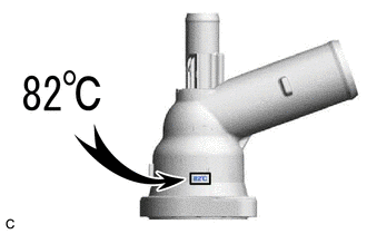
The valve opening temperature is inscribed on the water inlet with thermostat sub-assembly.

(a) Immerse the water inlet with thermostat sub-assembly in water and then gradually heat the water.
NOTICE:
Do not allow any water to come into contact with the connector of the water inlet with thermostat sub-assembly.
(b) Check that the valve of the water inlet with thermostat sub-assembly opens at the specified temperature.
Standard Valve Opening Temperature:
80 to 84°C (176 to 183°F)
If the result is not as specified, replace the water inlet with thermostat sub-assembly.
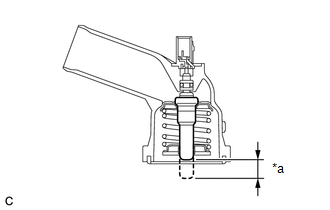
| (c) Check the valve lift. Standard Valve Lift: 8.0 mm (0.315 in.) or more at 95°C (203°F) If the result is not as specified, replace the water inlet with thermostat sub-assembly. |
|
(d) Check that the valve is fully closed when the water inlet with thermostat sub-assembly is at low temperatures (below 72°C (162°F)).
If it is not fully closed, replace the water inlet with thermostat sub-assembly.
(e) Measure the resistance according to the value(s) in the table below.
Standard Resistance:
|
Tester Connection | Condition |
Specified Condition |
|---|---|---|
|
1 - 2 | Always |
10.5 to 14.3 Ω |
If the result is not as specified, replace the water inlet with thermostat sub-assembly.


