Toyota Corolla Cross: Evaporative Emission System Purge Control Valve "A" Circuit Open (P044313)
DESCRIPTION
To reduce hydrocarbon (HC) emissions, evaporated fuel from the fuel tank is routed through a canister to the intake manifold for combustion in the cylinders.
The ECM changes the duty signals to the purge VSV (No. 1 vacuum switching valve assembly) so that the intake amount of evaporated fuel routed to the cylinders is appropriate for the driving conditions (engine load, engine speed, vehicle speed, etc.) after the engine is warmed up.
|
DTC No. | Detection Item |
DTC Detection Condition | Trouble Area |
MIL | Note |
|---|---|---|---|---|---|
|
P044313 | Evaporative Emission System Purge Control Valve "A" Circuit Open |
Both of the following conditions are met (1 trip detection logic):
|
| Comes on |
|
CONFIRMATION DRIVING PATTERN
HINT:
- After repair has been completed, clear the DTC and then check that the vehicle has returned to normal by performing the following All Readiness check procedure.
Click here
.gif)
- When clearing the permanent DTCs, refer to the "CLEAR PERMANENT DTC" procedure.
Click here
- Connect the GTS to the DLC3.
- Turn the ignition switch to ON.
- Turn the GTS on.
- Clear the DTCs (even if no DTCs are stored, perform the clear DTC procedure).
- Turn the ignition switch off and wait for at least 30 seconds.
- Turn the ignition switch to ON.
- Turn the GTS on.
- Put the engine in Inspection Mode (Maintenance Mode).
Click here
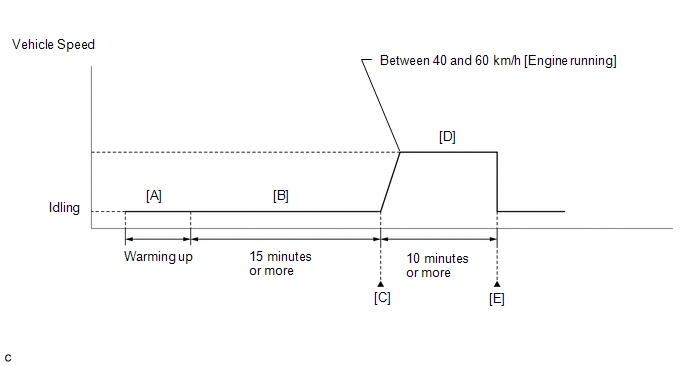
- Start the engine and warm it up until the engine coolant temperature is 75°C (167°F) or higher [A].
HINT:
The A/C switch and all accessories should be off.
- Idle the engine for 15 minutes or more [B].
HINT:
Check the Data List item "EVAP (Purge) VSV". When the value of this item is between 5 and 95%, the judgment will be performed.
- Enter the following menus: Powertrain / Engine / Trouble Codes [C].
- Read the pending DTCs.
HINT:
- If a pending DTC is output, the system is malfunctioning.
- If a pending DTC is not output, perform the following procedure.
- Enter the following menus: Powertrain / Engine / Utility / All Readiness.
- Input the DTC: P044313.
- Check the DTC judgment result.
GTS Display
Description
NORMAL
- DTC judgment completed
- System normal
ABNORMAL
- DTC judgment completed
- System abnormal
INCOMPLETE
- DTC judgment not completed
- Perform driving pattern after confirming DTC enabling conditions
HINT:
- If the judgment result shows NORMAL, the system is normal.
- If the judgment result shows ABNORMAL, the system is malfunctioning.
- [A] to [C]: Normal judgment procedure.
The normal judgment procedure is used to complete DTC judgment and also used when clearing permanent DTCs.
- When clearing the permanent DTCs, do not disconnect the cable from the battery terminal or attempt to clear the DTCs during this procedure, as doing so will clear the universal trip and normal judgment histories.
- With the engine running, drive the vehicle at a constant speed between 40 and 60 km/h (25 and 37 mph) for 10 minutes or more [D].
CAUTION:
When performing the confirmation driving pattern, obey all speed limits and traffic laws.
HINT:
If the engine stops, further depress the accelerator pedal to restart the engine.
- Enter the following menus: Powertrain / Engine / Trouble Codes [E].
- Read the pending DTCs.
HINT:
- If a pending DTC is output, the system is malfunctioning.
- If a pending DTC is not output, perform the following procedure.
- Enter the following menus: Powertrain / Engine / Utility / All Readiness.
- Input the DTC: P044313.
- Check the DTC judgment result.
GTS Display
Description
NORMAL
- DTC judgment completed
- System normal
ABNORMAL
- DTC judgment completed
- System abnormal
INCOMPLETE
- DTC judgment not completed
- Perform driving pattern after confirming DTC enabling conditions
HINT:
- If the judgment result shows NORMAL, the system is normal.
- If the judgment result shows ABNORMAL, the system is malfunctioning.
- [A] to [E]: Normal judgment procedure.
The normal judgment procedure is used to complete DTC judgment and also used when clearing permanent DTCs.
- When clearing the permanent DTCs, do not disconnect the cable from the battery terminal or attempt to clear the DTCs during this procedure, as doing so will clear the universal trip and normal judgment histories.
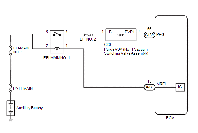
WIRING DIAGRAM
CAUTION / NOTICE / HINT
NOTICE:
- Inspect the fuses for circuits related to this system before performing the following procedure.
- Vehicle Control History may be stored in the hybrid vehicle control ECU assembly if the engine is malfunctioning. Certain vehicle condition information is recorded when Vehicle Control History is stored. Reading the vehicle conditions recorded in both the freeze frame data and Vehicle Control History can be useful for troubleshooting.
Click here
(Select Powertrain in Health Check and then check the time stamp data.)
- If any "Engine Malfunction" Vehicle Control History item has been stored in the hybrid vehicle control ECU assembly, make sure to clear it. However, as all Vehicle Control History items are cleared simultaneously, if any Vehicle Control History items other than "Engine Malfunction" are stored, make sure to perform any troubleshooting for them before clearing Vehicle Control History.
Click here
HINT:
Read freeze frame data using the GTS. The ECM records vehicle and driving condition information as freeze frame data the moment a DTC is stored. When troubleshooting, freeze frame data can help determine if the vehicle was moving or stationary, if the engine was warmed up or not, if the air fuel ratio was lean or rich, and other data from the time the malfunction occurred.
PROCEDURE
| 1. |
PERFORM ACTIVE TEST USING GTS (ACTIVATE THE EVAP PURGE VSV) |
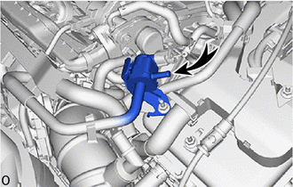
(a) Disconnect the fuel vapor feed hose assembly (canister side) of the purge VSV (No. 1 vacuum switching valve assembly).
(b) Put the engine in Inspection Mode (Maintenance Mode).
Powertrain > Hybrid Control > Utility|
Tester Display |
|---|
| Inspection Mode |
(c) Start the engine.
(d) Enter the following menus.
Powertrain > Engine > Active Test|
Tester Display |
|---|
| Activate the EVAP Purge VSV |
(e) When the purge VSV (No. 1 vacuum switching valve assembly) is operated using the GTS, check whether the port of the purge VSV (No. 1 vacuum switching valve assembly) applies suction your finger.
OK:
|
GTS Operation | Specified Condition |
|---|---|
|
ON | Purge VSV (No. 1 vacuum switching valve assembly) port applies suction to finger |
|
OFF | Purge VSV (No. 1 vacuum switching valve assembly) port applies no suction to finger |
HINT:
Jiggle the wire harness and connector to increase the likelihood of detecting malfunctions that do not always occur.
| OK | .gif) | CHECK FOR INTERMITTENT PROBLEMS |
|
.gif)
| 2. |
INSPECT PURGE VSV (NO. 1 VACUUM SWITCHING VALVE ASSEMBLY) |
Click here
| NG | | REPLACE PURGE VSV (NO. 1 VACUUM SWITCHING VALVE ASSEMBLY) |
|
| 3. |
CHECK TERMINAL VOLTAGE (POWER SOURCE OF PURGE VSV (NO. 1 VACUUM SWITCHING VALVE ASSEMBLY)) |
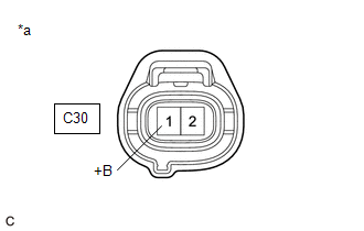
|
*a | Front view of wire harness connector (to Purge VSV (No. 1 Vacuum Switching Valve Assembly)) |
(a) Disconnect the purge VSV (No. 1 vacuum switching valve assembly) connector.
(b) Turn the ignition switch to ON.
(c) Measure the voltage according to the value(s) in the table below.
Standard Voltage:
|
Tester Connection | Condition |
Specified Condition |
|---|---|---|
|
C30-1 (+B) - Body ground |
Ignition switch ON | 11 to 14 V |
| NG | | REPAIR OR REPLACE HARNESS OR CONNECTOR (EFI-MAIN NO. 1 RELAY - PURGE VSV (NO. 1 VACUUM SWITCHING VALVE ASSEMBLY)) |
|
| 4. |
CHECK HARNESS AND CONNECTOR (PURGE VSV (NO. 1 VACUUM SWITCHING VALVE ASSEMBLY) - ECM) |
(a) Disconnect the purge VSV (No. 1 vacuum switching valve assembly) connector.
(b) Disconnect the ECM connector.
(c) Measure the resistance according to the value(s) in the table below.
Standard Resistance:
|
Tester Connection | Condition |
Specified Condition |
|---|---|---|
|
C30-2 (EVP1) - C139-66 (PRG) |
Always | Below 1 Ω |
|
C30-2 (EVP1) or C139-66 (PRG) - Body ground and other terminals |
Always | 10 kΩ or higher |
| OK | | REPLACE ECM |
| NG | | REPAIR OR REPLACE HARNESS OR CONNECTOR |


