Toyota Corolla Cross: Disassembly
DISASSEMBLY
CAUTION / NOTICE / HINT
COMPONENTS (DISASSEMBLY)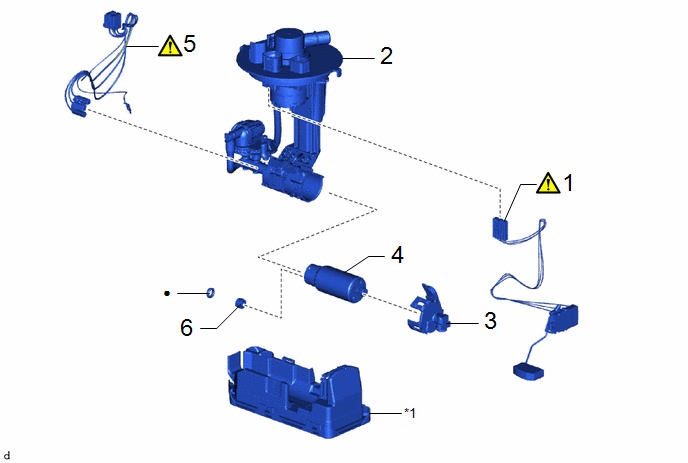
|
Procedure | Part Name Code |
.png) |
.png) |
 |
|---|---|---|---|---|---|
|
1 | FUEL SENDER GAUGE ASSEMBLY |
83320 |
|
- | - |
|
2 | FUEL SUCTION PLATE SUB-ASSEMBLY |
77024A | - |
- | - |
|
3 | NO. 2 FUEL SUCTION SUPPORT |
77175 | - |
- | - |
|
4 | FUEL PUMP |
23221 | - |
- | - |
|
5 | FUEL PUMP HARNESS |
77785 |
|
- | - |
|
6 | FUEL PUMP SPACER |
23225A | - |
- | - |
.gif)
|
*1 | FUEL SUB-TANK SUB-ASSEMBLY |
- | - |
|
● | Non-reusable part |
- | - |
CAUTION / NOTICE / HINT
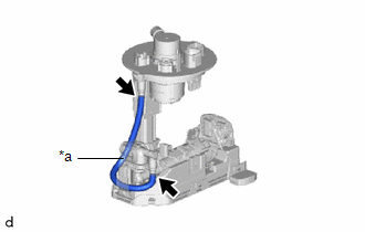
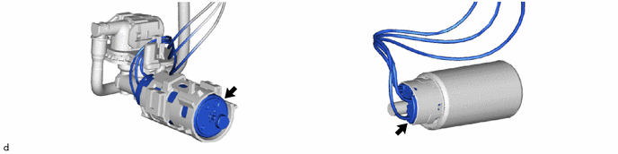
NOTICE:
Do not disconnect the tube shown in the illustration when disassembling the fuel suction tube with pump and gauge assembly. Doing so will cause reassembly of the fuel suction tube with pump and gauge assembly to be impossible as the tube is pressed into the fuel suction plate sub-assembly.
|
*a | Tube |
PROCEDURE
1. REMOVE FUEL SENDER GAUGE ASSEMBLY
|
|
Click here |
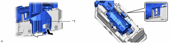
2. REMOVE FUEL SUCTION PLATE SUB-ASSEMBLY
|
*1 | Fuel Suction Plate Sub-assembly |
- | - |
.png) |
Pull |
.png) |
Slide |
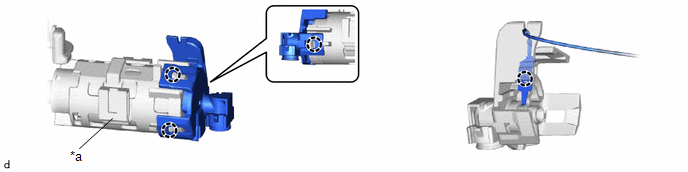
3. REMOVE NO. 2 FUEL SUCTION SUPPORT
|
*a | Fuel Tube Supporter |
- | - |
4. REMOVE FUEL PUMP
5. REMOVE FUEL PUMP HARNESS
|
|
NOTICE: Do not damage the wire harness. |
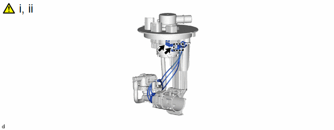
(1) Disengage the clamp.
NOTICE:
When disengaging each wire harness from the clamp, disengage one wire at a time.
(2) Disconnect the 2 fuel pump harness connectors and remove the fuel pump harness from the fuel suction plate sub-assembly.
6. REMOVE FUEL PUMP SPACER

|
*1 | O-ring |
*2 | Fuel Pump Spacer |


