Toyota Corolla Cross: Cooling Fan Ecu
On-vehicle Inspection
ON-VEHICLE INSPECTION
PROCEDURE
1. CHECK COOLING FAN SYSTEM
(a) Check and ensure the following conditions:
(1) The ignition switch is off.
(2) The engine coolant temperature is less than 86 °C (187 °F).
(3) The auxiliary battery voltage is between 11 to 14 V.
(4) The A/C switch is off.
(b) Connect the pickup of a clamp-on ammeter around either of the 2 wires for the cooling fan motor.
(c) Turn the ignition switch to ON and wait for approximately 10 seconds. Check that the cooling fan is not operating.
(d) Start the engine. Check that the cooling fan is not operating with the engine idling.
HINT:
- Make sure that the engine coolant temperature is less than 86 °C (187 °F).
- Turn the A/C switch off.
(e) Check that the cooling fan operate when the A/C switch is turned on.
(f) Measure the current while the cooling fan motor is turning.
Standard Current:
|
Item | Condition |
Specified Condition |
|---|---|---|
|
Cooling fan motor | 20°C (68°F) at 12 V |
7.4 to 10.9 A |
HINT:
The engine coolant temperature should be less than 86 °C (187 °F).
(g) Check that the cooling fan operate when the engine coolant temperature sensor connector is disconnected.
(h) Measure the current while the cooling fan motor is turning.
Standard Current:
|
Item | Condition |
Specified Condition |
|---|---|---|
|
Cooling fan motor | 20°C (68°F) at 12 V |
7.4 to 10.9 A |
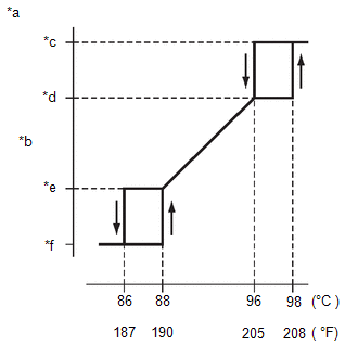
| (i) After the engine is warmed up, check that the cooling fan operate as shown in the illustration. HINT:
|
|