Toyota Corolla Cross: Installation
INSTALLATION
CAUTION / NOTICE / HINT
COMPONENTS (INSTALLATION)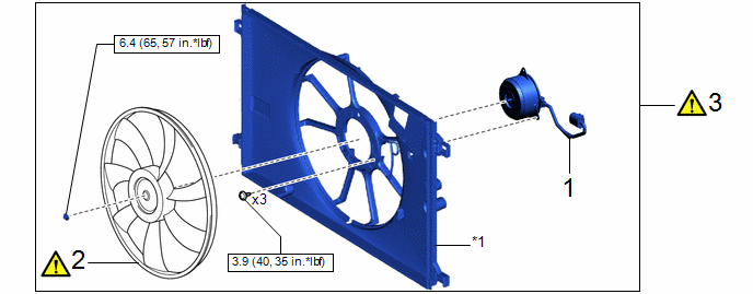
|
Procedure | Part Name Code |
.png) |
.png) |
 |
|---|---|---|---|---|---|
|
1 | COOLING FAN MOTOR |
16363 | - |
- | - |
|
2 | FAN |
16361 |
|
- | - |
|
3 | FAN WITH MOTOR ASSEMBLY |
- |
|
- | - |
|
*1 | SHROUD ASSY FAN |
- | - |
.png) |
N*m (kgf*cm, ft.*lbf): Specified torque |
- | - |

|
Procedure | Part Name Code |
|
|
| |
|---|---|---|---|---|---|
|
4 | NO. 2 RADIATOR AIR GUIDE |
16594A | - |
- | - |
|
5 | NO. 2 RADIATOR HOSE |
16572D | - |
- | - |

|
Procedure | Part Name Code |
|
|
| |
|---|---|---|---|---|---|
|
6 | RADIATOR SUPPORT SUB-ASSEMBLY |
53201 | - |
- | - |
|
7 | HOOD LOCK CABLE ASSEMBLY |
53630 | - |
- | - |
|
8 | HOOD LOCK CONTROL LEVER SUB-ASSEMBLY |
53601 | - |
- | - |
|
9 | INLET NO. 2 AIR CLEANER |
17752 | - |
- | - |
|
10 | INLET NO. 1 AIR CLEANER |
17751 | - |
- | - |
|
11 | INLET NO. 3 AIR CLEANER |
17753 | - |
- | - |
|
12 | NO. 1 RADIATOR TO SUPPORT SEAL |
16561C | - |
- | - |
|
|
N*m (kgf*cm, ft.*lbf): Specified torque |
 |
MP grease |
|
Procedure | Part Name Code |
|
|
| |
|---|---|---|---|---|---|
|
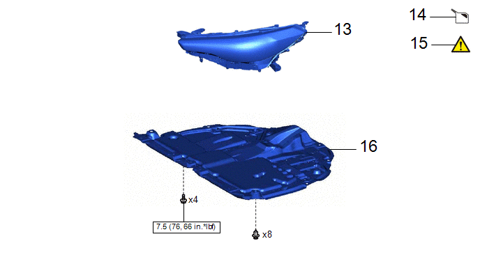
13 | HEADLIGHT ASSEMBLY |
- | - |
- | - |
|
14 | ADD ENGINE COOLANT |
- | - |
|
- |
| 15 |
INSPECT FOR COOLANT LEAK |
- |
|
- | - |
|
16 | NO. 1 ENGINE UNDER COVER ASSEMBLY |
51410 | - |
- | - |
|
|
N*m (kgf*cm, ft.*lbf): Specified torque |
- | - |
PROCEDURE
1. INSTALL COOLING FAN MOTOR
Torque:
3.9 N·m {40 kgf·cm, 35 in·lbf}
2. INSTALL FAN
|
|
NOTICE: Do not reverse the position of the fan when installing them. Doing so may damage the parts. |
Torque:
6.4 N·m {65 kgf·cm, 57 in·lbf}
3. INSTALL FAN WITH MOTOR ASSEMBLY

(1) Engage the 2 guides.
(2) Engage the 2 claws to install the fan with motor assembly to the radiator assembly.
NOTICE:
Do not damage the radiator assembly when installing the fan with motor assembly.

(1) Engage the 2 wire harness clamps.
(2) Connect the connector.
4. INSTALL NO. 2 RADIATOR AIR GUIDE
5. CONNECT NO. 2 RADIATOR HOSE
6. INSTALL RADIATOR SUPPORT SUB-ASSEMBLY
Torque:
12.5 N·m {127 kgf·cm, 9 ft·lbf}
7. INSTALL HOOD LOCK CABLE ASSEMBLY
8. INSTALL HOOD LOCK CONTROL LEVER SUB-ASSEMBLY
Click here .gif)
9. INSTALL INLET NO. 2 AIR CLEANER
10. INSTALL INLET NO. 1 AIR CLEANER
Torque:
4.0 N·m {41 kgf·cm, 35 in·lbf}
11. INSTALL INLET NO. 3 AIR CLEANER
12. INSTALL NO. 1 RADIATOR TO SUPPORT SEAL
13. INSTALL HEADLIGHT ASSEMBLY
- for Bulb Type Clearance Light
Click here
- for LED Type Clearance Light
Click here
14. ADD ENGINE COOLANT
Click here
15. INSPECT FOR COOLANT LEAK
Click here
16. INSTALL NO. 1 ENGINE UNDER COVER ASSEMBLY
Click here


