Toyota Corolla Cross: Brake Switch "B" Circuit Short to Battery (P070312)
DESCRIPTION
The purpose of this circuit is to prevent the engine from stalling when the brakes are suddenly applied while driving with lock-up on.
When the brake pedal is depressed, the stop light switch assembly sends a signal to the TCM. Then the TCM cancels the operation of the lock-up clutch while braking is in progress.
|
DTC No. |
Detection Item |
DTC Detection Condition |
Trouble Area |
MIL |
Memory |
Note |
|---|---|---|---|---|---|---|
|
P070312 |
Brake Switch "B" Circuit Short to Battery |
All of the following conditions are met (2-trip detection logic):
|
|
Comes on |
DTC stored |
SAE Code: P0724 |
MONITOR DESCRIPTION
This DTC indicates that the stop light switch assembly is remaining on. When the stop light switch assembly remains on during "stop and go" driving, the TCM interprets this as a malfunction of the stop light switch assembly, illuminates the MIL and stores this DTC. The vehicle must STOP (less than 3 km/h (2 mph)) and GO (30 km/h (19 mph) or more) five times for two consecutive driving cycles in order to store this DTC.
MONITOR STRATEGY
|
Related DTCs |
P0724: Stop light switch/Verify switch input |
|
Required sensors/Components |
Stop light switch assembly |
|
Frequency of operation |
Continuous |
|
Duration |
GO and STOP 5 times |
|
MIL operation |
2 driving cycles |
|
Sequence of operation |
None |
TYPICAL ENABLING CONDITIONS
The stop light switch remains on during GO and STOP driving 5 times.
GO and STOP are defined as follows:
|
The monitor will run whenever the following DTCs are not stored |
None |
|
GO (Vehicle speed is 30 km/h (18.65 mph) or more) |
Once |
|
STOP (Vehicle speed is less than 3 km/h (1.86 mph)) |
Once |
|
Auxiliary battery voltage |
8 V or more |
|
Ignition switch |
ON |
|
Starter |
OFF |
TYPICAL MALFUNCTION THRESHOLDS
|
Stop light switch |
ON |
CONFIRMATION DRIVING PATTERN
CAUTION:
When performing the confirmation driving pattern, obey all speed limits and traffic laws.
HINT:
- After repairs have been completed, clear the DTCs and then check that the vehicle has returned to normal by performing the following All Readiness check procedure.
- When clearing the permanent DTCs, refer to the Clear Permanent DTC procedure.
Click here
.gif)
- Clear the DTCs (even if no DTCs are stored, perform the clear DTC procedure).
- Turn the ignition switch off and wait for 2 minutes or more.
- Turn the ignition switch to ON and turn the GTS on.
- Start the engine.
- Repeat the following procedure 5 times [*1]:
- Accelerate the vehicle to 30 km/h (19 mph) or more, depress the brake
pedal and decelerate the vehicle to less than 3 km/h (2 mph).
HINT:
[*1]: Normal judgment procedure.
The normal judgment procedure is used to complete DTC judgment and also used when clearing permanent DTCs.
- Accelerate the vehicle to 30 km/h (19 mph) or more, depress the brake
pedal and decelerate the vehicle to less than 3 km/h (2 mph).
- Stop the vehicle.
- Enter the following menus: Powertrain / Transmission / Utility / All Readiness.
- Input the DTC: P070312.
- Check the DTC judgment result.
GTS Display
Description
NORMAL
- DTC judgment completed
- System normal
ABNORMAL
- DTC judgment completed
- System abnormal
INCOMPLETE
- DTC judgment not completed
- Perform driving pattern after confirming DTC enabling conditions
N/A
- Unable to perform DTC judgment
- Number of DTCs which do not fulfill DTC preconditions has reached ECU memory limit
HINT:
- If the judgment result shows NORMAL, the system is normal.
- If the judgment result shows ABNORMAL, the system has a malfunction.
- If the judgment result shows INCOMPLETE or N/A, perform the normal judgment procedure again.
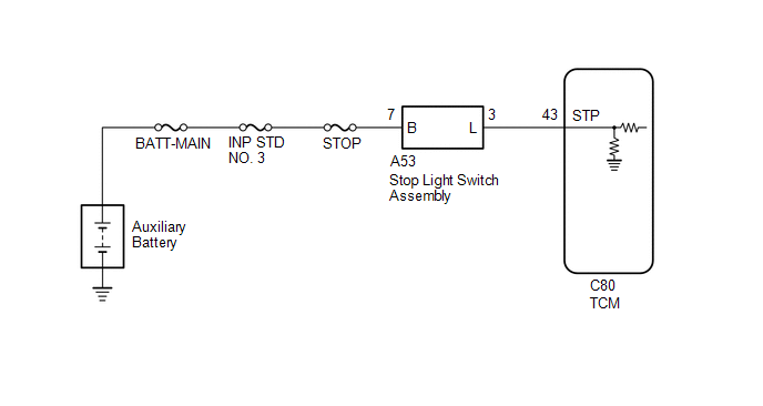
WIRING DIAGRAM
CAUTION / NOTICE / HINT
CAUTION:
- Strictly observe posted speed limits, traffic laws and road conditions.
.png)
- Do not drive the vehicle with the cable of the GTS contacting the pedals, shift lever or steering wheel.
- Driving the vehicle with the cable of the GTS contacting these areas could impede vehicle control, resulting in a serious accident.
- Do not operate the GTS while driving the vehicle.
.png)
- Operating the GTS while driving the vehicle will prevent you from paying sufficient attention to vehicle surroundings, and could result in a serious accident.
NOTICE:
- Perform the universal trip to clear permanent DTCs.
Click here
- Perform registration and/or initialization when parts related to the continuously
variable transaxle system are replaced.
Click here
- Check that no DTCs are stored after performing initialization.
Click here
- Inspect the fuses for circuits related to this system before performing the following procedure.
PROCEDURE
|
1. |
READ VALUE USING GTS (STOP LIGHT SW) |
(a) Enter the following menus:
(b) According to the display on the GTS, read the Data List while the vehicle is being driven.
Powertrain > Transmission > Data List|
Tester Display |
Measurement Item |
Range |
Normal Condition |
Diagnostic Note |
|---|---|---|---|---|
|
Stop Light SW |
Stop light switch assembly status |
OFF or ON |
|
- |
|
Tester Display |
|---|
|
Stop Light SW |
OK:
On the GTS screen, ON or OFF is displayed accordingly.
NOTICE:
In the table above, the conditions listed under "Normal Condition" are reference conditions. Do not depend solely on these reference conditions when deciding whether a part is faulty or not.
| OK | .gif) |
CHECK FOR INTERMITTENT PROBLEMS Click here Click here |
|
.gif)
|
2. |
CHECK STOP LIGHT SWITCH ASSEMBLY INSTALLATION |
Click here
OK:
Stop light switch assembly is installed correctly.
| NG | |
SECURELY REINSTALL STOP LIGHT SWITCH ASSEMBLY |
|
|
3. |
INSPECT STOP LIGHT SWITCH ASSEMBLY |
Click here
| NG | |
REPLACE STOP LIGHT SWITCH ASSEMBLY |
|
|
4. |
CHECK TERMINAL VOLTAGE (STP VOLTAGE) |
(a) Disconnect the TCM connector.
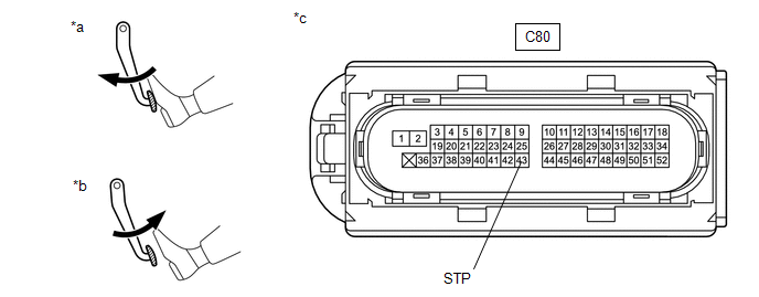
|
*a |
Brake pedal depressed |
*b |
Brake pedal released |
|
*c |
Front view of wire harness connector (to TCM) |
- |
- |
(b) Measure the voltage according to the value(s) in the table below.
Standard Voltage:
|
Tester Connection |
Condition |
Specified Condition |
|---|---|---|
|
C80-43 (STP) - Body ground |
Brake pedal released |
Below 1.5 V |
|
Brake pedal depressed |
7.5 to 14 V |
| NG | |
REPAIR OR REPLACE HARNESS OR CONNECTOR |
|
|
5. |
REPLACE TCM |
Click here
| NEXT | |
PERFORM REGISTRATION AND INITIALIZATION for Registration: Click here for Initialization: Click here |


