Toyota Corolla Cross: Transmission Range Sensor "A" Circuit Open (P070513,P070562)
DESCRIPTION
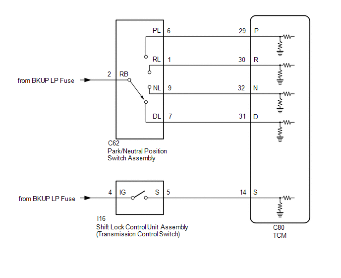
The park/neutral position switch assembly and transmission control switch (shift lock control unit assembly) detect the shift lever position and send signals to the TCM.
|
DTC No. |
Detection Item |
DTC Detection Condition |
Trouble Area |
MIL |
Memory |
Note |
|---|---|---|---|---|---|---|
|
P070513 |
Transmission Range Sensor "A" Circuit Open |
P, R, N and D input signals are all OFF simultaneously for 60 seconds or more (2-trip detection logic). |
|
Comes on |
DTC stored |
SAE Code: P0705 |
|
P070562 |
Transmission Range Sensor "A" Signal Compare Failure |
Either of the following conditions is met for 2 seconds or more (2-trip detection logic).
|
|
Comes on |
DTC stored |
SAE Code: P0705 |
MONITOR DESCRIPTION
These DTCs indicate a problem with the park/neutral position switch assembly, transmission control switch or wire harness of their circuits.
The park/neutral position switch assembly detects the shift lever position and sends a signal to the TCM. For safety, the park/neutral position switch assembly detects the shift lever position so that the engine can be started only when the shift lever is in P or N.
The park/neutral position switch assembly sends a signal to the TCM according to the shift lever position (P, R, N or D).
The TCM determines that there is a problem with the switch or related parts if it receives more than 1 position signal simultaneously. The TCM will then illuminate the MIL and store a DTC.
MONITOR STRATEGY
|
Related DTCs |
P0705: Transmission range switch/Verify switch input |
|
Required sensors/Components |
Park/neutral position switch assembly Transmission control switch |
|
Frequency of operation |
Continuous |
|
Duration |
Condition (A): 2 sec. Condition (B): 2 sec. Condition (C): 60 sec. |
|
MIL operation |
2 driving cycles |
|
Sequence of operation |
None |
TYPICAL ENABLING CONDITIONS
All|
Ignition switch |
ON |
|
Auxiliary battery voltage |
8 V or more |
|
Starter |
OFF |
|
One of the following conditions is met: |
- |
|
P position switch |
ON |
|
N position switch |
ON |
|
R position switch |
ON |
TYPICAL MALFUNCTION THRESHOLDS
Either of the following conditions is met: Condition (A), (B) or (C)
Condition (A)|
Any two of the following conditions are met: |
Conditions 1, 2 and 3 |
|
1. One of the following conditions is met: |
Conditions (a) or (b) |
|
(a) P position switch |
ON |
|
(b) N position switch |
ON |
|
2. R position switch |
ON |
|
3. D position switch |
ON |
|
S position switch |
ON |
|
All of the following conditions are met: |
- |
|
P position switch |
OFF |
|
N position switch |
OFF |
|
R position switch |
OFF |
|
D position switch |
OFF |
CONFIRMATION DRIVING PATTERN
HINT:
- After repairs have been completed, clear the DTCs and then check that the vehicle has returned to normal by performing the following All Readiness check procedure.
- When clearing the permanent DTCs, refer to the Clear Permanent DTC procedure.
Click here
.gif)
- Clear the DTCs (even if no DTCs are stored, perform the clear DTC procedure).
- Turn the ignition switch off and wait for 2 minutes or more.
- Turn the ignition switch to ON and turn the GTS on.
- Wait with the shift lever in each position (P, R, N or D) for 60 seconds or more each with the ignition switch to ON. [*1]
- Wait for 2 seconds or more with the shift lever in M. [*2]
HINT:
[*1] and [*2]: Normal judgment procedure.
The normal judgment procedure is used to complete DTC judgment and also used when clearing permanent DTCs.
- Enter the following menus: Powertrain / Transmission / Utility / All Readiness.
- Input the DTC: P070513 or P070562.
- Check the DTC judgment result.
GTS Display
Description
NORMAL
- DTC judgment completed
- System normal
ABNORMAL
- DTC judgment completed
- System abnormal
INCOMPLETE
- DTC judgment not completed
- Perform driving pattern after confirming DTC enabling conditions
N/A
- Unable to perform DTC judgment
- Number of DTCs which do not fulfill DTC preconditions has reached ECU memory limit
HINT:
- If the judgment result shows NORMAL, the system is normal.
- If the judgment result shows ABNORMAL, the system has a malfunction.
- If the judgment result shows INCOMPLETE or N/A, perform the normal judgment procedure again.
WIRING DIAGRAM
CAUTION / NOTICE / HINT
NOTICE:
- Perform the universal trip to clear permanent DTCs.
Click here
- Perform registration and/or initialization when parts related to the continuously
variable transaxle system are replaced.
Click here
- Check that no DTCs are stored after performing initialization.
Click here
- Inspect the fuses for circuits related to this system before performing the following inspection procedure.
PROCEDURE
|
1. |
READ VALUE USING GTS (SHIFT SW STATUS) |
(a) Enter the following menus:
(b) According to the display on the GTS, read the Data List.
Powertrain > Transmission > Data List|
Tester Display |
Measurement Item |
Range |
Normal Condition |
Diagnostic Note |
|---|---|---|---|---|
|
Shift SW Status (P Range) |
Park/neutral position switch assembly status |
OFF or ON |
|
When the shift lever position displayed on the GTS differs from the actual position, the adjustment of the park/neutral position switch assembly or shift cable may be incorrect. |
|
Shift SW Status (R Range) |
Park/neutral position switch assembly status |
OFF or ON |
|
When the shift lever position displayed on the GTS differs from the actual position, the adjustment of the park/neutral position switch assembly or shift cable may be incorrect. |
|
Shift SW Status (N Range) |
Park/neutral position switch assembly status |
OFF or ON |
|
When the shift lever position displayed on the GTS differs from the actual position, the adjustment of the park/neutral position switch assembly or shift cable may be incorrect. |
|
Shift SW Status (D Range) |
Park/neutral position switch assembly status |
OFF or ON |
|
When the shift lever position displayed on the GTS differs from the actual position, the adjustment of the park/neutral position switch assembly or shift cable may be incorrect. |
|
Tester Display |
|---|
|
Shift SW Status (P Range) |
|
Shift SW Status (R Range) |
|
Shift SW Status (N Range) |
|
Shift SW Status (D Range) |
|
Result |
Proceed to |
|---|---|
|
Data List values are normal |
A |
|
Data List values are not normal |
B |
| B | .gif) |
GO TO STEP 7 |
|
.gif)
|
2. |
READ VALUE USING GTS (SHIFT SW STATUS (S RANGE)) |
(a) Enter the following menus:
(b) According to the display on the GTS, read the Data List.
Powertrain > Transmission > Data List|
Tester Display |
Measurement Item |
Range |
Normal Condition |
Diagnostic Note |
|---|---|---|---|---|
|
Shift SW Status (S Range) |
Transmission control switch status |
OFF or ON |
|
- |
|
Tester Display |
|---|
|
Shift SW Status (S Range) |
|
Result |
Proceed to |
|---|---|
|
Data List value is normal |
A |
|
Data List value is not normal |
B |
| A | |
CHECK FOR INTERMITTENT PROBLEMS Click here Click here |
|
|
3. |
CHECK HARNESS AND CONNECTOR (SHIFT LOCK CONTROL UNIT ASSEMBLY (POWER SOURCE)) |
|
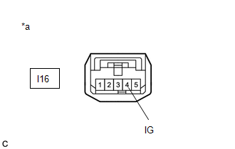
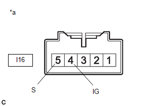
*a |
Front view of wire harness connector (to Shift Lock Control Unit Assembly (Transmission Control Switch)) |
(a) Disconnect the shift lock control unit assembly connector.
(b) Measure the voltage according to the value(s) in the table below.
Standard Voltage:
|
Tester Connection |
Condition |
Specified Condition |
|---|---|---|
|
I16-4 (IG) - Body ground |
Ignition switch ON |
11 to 14 V |
|
I16-4 (IG) - Body ground |
Ignition switch off |
Below 1 V |
(c) Connect the shift lock control unit assembly connector.
| NG | |
REPAIR OR REPLACE HARNESS OR CONNECTOR (SHIFT LOCK CONTROL UNIT ASSEMBLY (POWER SOURCE)) |
|
|
4. |
INSPECT SHIFT LOCK CONTROL UNIT ASSEMBLY (TRANSMISSION CONTROL SWITCH) |
|
(a) Disconnect the shift lock control unit assembly connector. |
|
(b) Measure the resistance according to the value(s) in the table below.
Standard Resistance:
|
Tester Connection |
Condition |
Specified Condition |
|---|---|---|
|
4 (IG) - 5 (S) |
Shift lever in M, "+" or "- " |
Below 1 Ω |
|
4 (IG) - 5 (S) |
Shift lever not in M, "+" or "-" |
10 kΩ or higher |
(c) Connect the shift lock control unit assembly connector.
| NG | |
REPLACE SHIFT LOCK CONTROL UNIT ASSEMBLY |
|
|
5. |
CHECK HARNESS AND CONNECTOR (SHIFT LOCK CONTROL UNIT ASSEMBLY - TCM) |
(a) Disconnect the I16 shift lock control unit assembly connector.
(b) Disconnect the C80 TCM connector.
(c) Measure the resistance according to the value(s) in the table below.
Standard Resistance:
|
Tester Connection |
Condition |
Specified Condition |
|---|---|---|
|
I16-5 (S) - C80-14 (S) |
Always |
Below 1 Ω |
|
I16-5 (S) or C80-14 (S) - Body ground |
Always |
10 kΩ or higher |
(d) Connect the C80 TCM connector.
(e) Connect the I16 shift lock control unit assembly connector.
| NG | |
REPAIR OR REPLACE HARNESS OR CONNECTOR (SHIFT LOCK CONTROL UNIT ASSEMBLY - TCM) |
|
|
6. |
REPLACE TCM |
Click here
| NEXT | |
PERFORM REGISTRATION AND INITIALIZATION for Registration: Click here for Initialization: Click here |
|
7. |
CHECK HARNESS AND CONNECTOR (AUXILIARY BATTERY - PARK/NEUTRAL POSITION SWITCH ASSEMBLY) |
|
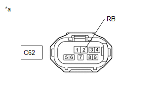
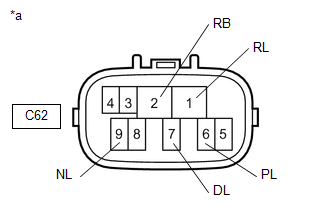
*a |
Front view of wire harness connector (to Park/Neutral Position Switch Assembly) |
(a) Disconnect the park/neutral position switch assembly connector.
(b) Measure the voltage according to the value(s) in the table below.
Standard Voltage:
|
Tester Connection |
Condition |
Specified Condition |
|---|---|---|
|
C62-2 (RB) - Body ground |
Ignition switch ON |
11 to 14 V |
|
C62-2 (RB) - Body ground |
Ignition switch off |
Below 1 V |
(c) Connect the park/neutral position switch assembly connector.
| NG | |
REPAIR OR REPLACE HARNESS OR CONNECTOR (AUXILIARY BATTERY - PARK/NEUTRAL POSITION SWITCH ASSEMBLY) |
|
|
8. |
INSPECT PARK/NEUTRAL POSITION SWITCH ASSEMBLY |
|
(a) Disconnect the park/neutral position switch assembly connector. |
|
(b) Measure the resistance according to the value(s) in the table below.
Standard Resistance:
|
Tester Connection |
Condition |
Specified Condition |
|---|---|---|
|
2 (RB) - 6 (PL) |
Shift lever in P |
Below 1 Ω |
|
Shift lever not in P |
10 kΩ or higher |
|
|
2 (RB) - 1 (RL) |
Shift lever in R |
Below 1 Ω |
|
Shift lever not in R |
10 kΩ or higher |
|
|
2 (RB) - 9 (NL) |
Shift lever in N |
Below 1 Ω |
|
Shift lever not in N |
10 kΩ or higher |
|
|
2 (RB) - 7 (DL) |
Shift lever in D, M, "+" or "-" |
Below 1 Ω |
|
Shift lever not in D, M, "+" or "-" |
10 kΩ or higher |
(c) Connect the park/neutral position switch assembly connector.
| NG | |
REPLACE PARK/NEUTRAL POSITION SWITCH ASSEMBLY
|
|
|
9. |
CHECK HARNESS AND CONNECTOR (PARK/NEUTRAL POSITION SWITCH ASSEMBLY - TCM) |
(a) Disconnect the C62 park/neutral position switch assembly connector.
(b) Disconnect the C80 TCM connector.
(c) Measure the resistance according to the value(s) in the table below.
Standard Resistance:
|
Tester Connection |
Condition |
Specified Condition |
|---|---|---|
|
C62-6 (PL) - C80-29 (P) |
Always |
Below 1 Ω |
|
C62-1 (RL) - C80-30 (R) |
Always |
Below 1 Ω |
|
C62-9 (NL) - C80-32 (N) |
Always |
Below 1 Ω |
|
C62-7 (DL) - C80-31 (D) |
Always |
Below 1 Ω |
|
C62-6 (PL) or C80-29 (P) - Body ground and other terminals |
Always |
10 kΩ or higher |
|
C62-1 (RL) or C80-30 (R) - Body ground and other terminals |
Always |
10 kΩ or higher |
|
C62-9 (NL) or C80-32 (N) - Body ground and other terminals |
Always |
10 kΩ or higher |
|
C62-7 (DL) or C80-31 (D) - Body ground and other terminals |
Always |
10 kΩ or higher |
(d) Connect the C80 TCM connector.
(e) Connect the C62 park/neutral position switch assembly connector.
| NG | |
REPAIR OR REPLACE HARNESS OR CONNECTOR (PARK/NEUTRAL POSITION SWITCH ASSEMBLY - TCM) |
|
|
10. |
REPLACE TCM |
Click here
| NEXT | |
PERFORM REGISTRATION AND INITIALIZATION for Registration: Click here for Initialization: Click here |


