Toyota Corolla Cross: Back Door Entry Lock and Unlock Functions do not Operate
DESCRIPTION
If the entry lock and unlock functions do not operate for the back door only, the request code may not be being transmitted from the back door. If the entry functions for other doors operate properly, communication between the electrical key transmitter sub-assembly and door control receiver is normal. In this case, there may be a problem with request code transmission (communication between the certification ECU (smart key ECU assembly) and electrical key antenna (outside luggage compartment)) or there may be wave interference.
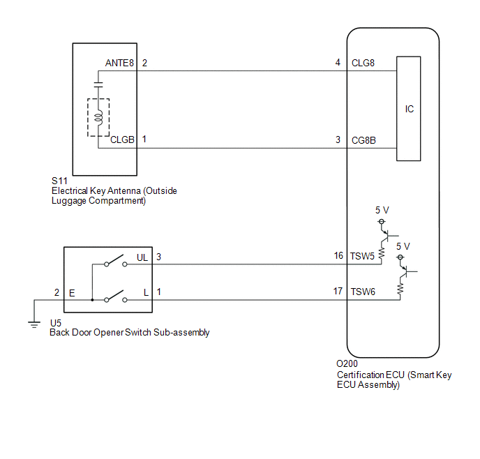
WIRING DIAGRAM
CAUTION / NOTICE / HINT
NOTICE:
- When using the GTS with the ignition switch off, connect the GTS to the DLC3 and turn a courtesy light switch on and off at intervals of 1.5 seconds or less until communication between the GTS and the vehicle begins. Then select the vehicle type under manual mode and enter the following menus: Body Electrical / Smart Key. While using the GTS, periodically turn a courtesy light switch on and off at intervals of 1.5 seconds or less to maintain communication between the GTS and the vehicle.
- The smart key system (for Entry Function) uses the CAN communication system. Inspect the communication function by following How to Proceed with Troubleshooting. Troubleshoot the smart key system (for Entry Function) after confirming that the communication systems are functioning properly.
Click here
.gif)
- Before replacing the certification ECU (smart key ECU assembly), refer to Precaution.
Click here
- Check that there are no electrical key transmitter sub-assemblies in the vehicle.
- After repair, confirm that no DTCs are output.
HINT:
- If the back door entry lock and unlock function does not operate, the cause of the malfunction may be stored in the certification ECU (smart key ECU assembly).
- If the cause of the malfunction is stored in the certification ECU (smart key ECU assembly), the following table is helpful in checking whether the malfunction was caused by wave interference.
|
Tester Display |
|---|
| Vehicle Control History (RoB) |
PROCEDURE
| 1. |
CHECK POWER DOOR LOCK CONTROL SYSTEM |
(a) When the door control switch on the multiplex network master switch assembly is operated, check that the back door lock and unlock according to the switch operation.
Click here
OK:
Back door lock/unlock operate normally.
| NG | .gif) | GO TO POWER DOOR LOCK CONTROL SYSTEM |
|
.gif)
| 2. |
CHECK WAVE ENVIRONMENT |
| (a) Bring the electrical key transmitter sub-assembly approximately 0.3 m (0.984 ft.) from the electrical key antenna (outside luggage compartment) and perform an entry back door open/lock function check. Click here HINT:
|
|
.png)
| Result |
Proceed to |
|---|---|
| Entry function does not operate normally |
A |
| Entry function operates normally |
B |
| B |
| AFFECTED BY WAVE INTERFERENCE |
|
| 3. |
READ VALUE USING GTS (TRUNK LID/BACK DOOR LOCK SWITCH, TRUNK LID/BACK DOOR UNLOCK SWITCH) |
(a) Read the Data List according to the display on the GTS.
Body Electrical > Smart Key > Data List|
Tester Display | Measurement Item |
Range | Normal Condition |
Diagnostic Note |
|---|---|---|---|---|
|
Trunk Lid/Back Door Lock Switch |
Back door opener switch sub-assembly (lock switch) |
OFF or ON | OFF: Back door opener switch sub-assembly (lock switch) not pressed ON: Back door opener switch sub-assembly (lock switch) pressed |
|
| Trunk Lid/Back Door Unlock Switch |
Back door opener switch sub-assembly (open switch) |
OFF or ON | OFF: Back door opener switch sub-assembly (open switch) not pressed ON: Back door opener switch sub-assembly (open switch) pressed |
|
|
Tester Display |
|---|
| Trunk Lid/Back Door Lock Switch |
|
Trunk Lid/Back Door Unlock Switch |
OK:
The GTS display changes correctly in response to the operation of the back door opener switch sub-assembly.
| NG | | GO TO STEP 8 |
|
| 4. |
CHECK KEY DIAGNOSTIC MODE |
(a) Check the following antenna in key diagnostic mode.
Body Electrical > Smart Key > Utility|
Tester Display |
|---|
| Communication Check(Key Diag Mode) |
| (b) Select either channel 1 or channel 2 and perform the key diagnostic mode inspection for each channel. (1) Check the electrical key antenna (outside luggage compartment): When the electrical key transmitter sub-assembly is brought within 0.7 to 1 m (2.30 to 3.28 ft.) of the electrical key antenna (outside luggage compartment), check that the wireless buzzer sounds. HINT:
|
|
|
Result | Proceed to |
|---|---|
|
Wireless buzzer does not sound |
A |
| Wireless buzzer sounds |
B |
| B |
| REPLACE CERTIFICATION ECU (SMART KEY ECU ASSEMBLY) |
|
| 5. |
CHECK HARNESS AND CONNECTOR (ELECTRICAL KEY ANTENNA (OUTSIDE LUGGAGE COMPARTMENT) - CERTIFICATION ECU (SMART KEY ECU ASSEMBLY)) |
(a) Disconnect the O200 certification ECU (smart key ECU assembly) connector.
(b) Disconnect the S11 electrical key antenna (outside luggage compartment) connector.
(c) Measure the resistance according to the value(s) in the table below.
Standard Resistance:
|
Tester Connection | Condition |
Specified Condition |
|---|---|---|
|
O200-4 (CLG8) - S11-2 (ANTE8) |
Always | Below 1 Ω |
|
O200-3 (CG8B) - S11-1 (CLGB) |
Always | Below 1 Ω |
|
O200-4 (CLG8) or S11-2 (ANTE8) - Other terminals and body ground |
Always | 10 kΩ or higher |
|
O200-3 (CG8B) or S11-1 (CLGB) - Other terminals and body ground |
Always | 10 kΩ or higher |
(d) Reconnect the O200 certification ECU (smart key ECU assembly) connector.
| NG | | REPAIR OR REPLACE HARNESS OR CONNECTOR |
|
| 6. |
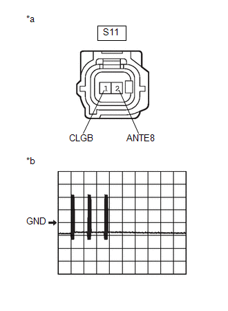
INSPECT CERTIFICATION ECU (SMART KEY ECU ASSEMBLY) (OUTPUT TO ELECTRICAL KEY ANTENNA (OUTSIDE LUGGAGE COMPARTMENT)) |
| (a) Using an oscilloscope, check the waveform. OK:
|
|
| OK | | REPLACE ELECTRICAL KEY ANTENNA (OUTSIDE LUGGAGE COMPARTMENT) |
|
| 7. |
CHECK ENTRY OPERATION |
(a) Connect all connectors and check that the function operates normally.
Click here
|
Result | Proceed to |
|---|---|
|
Entry function operates normally |
A |
| Entry function does not operate normally |
B |
| A |
| END (CONNECTOR WAS NOT CONNECTED SECURELY) |
| B |
| REPLACE CERTIFICATION ECU (SMART KEY ECU ASSEMBLY) |
| 8. |
CHECK HARNESS AND CONNECTOR (BACK DOOR OPENER SWITCH SUB-ASSEMBLY - CERTIFICATION ECU (SMART KEY ECU ASSEMBLY) AND BODY GROUND) |
(a) Disconnect the O200 certification ECU (smart key ECU assembly) connector.
(b) Disconnect the U5 back door opener switch sub-assembly connector.
(c) Measure the resistance according to the value(s) in the table below.
Standard Resistance:
|
Tester Connection | Condition |
Specified Condition |
|---|---|---|
|
O200-16 (TSW5) - U5-3 (UL) |
Always | Below 1 Ω |
|
O200-17 (TSW6) - U5-1 (L) |
Always | Below 1 Ω |
|
U5-2 (E) - Other terminals and body ground |
Always | Below 1 Ω |
|
O200-16 (TSW5) or U5-3 (UL) - Other terminals and body ground |
Always | 10 kΩ or higher |
|
O200-17 (TSW6) or U5-1 (L) - Other terminals and body ground |
Always | 10 kΩ or higher |
| NG | | REPAIR OR REPLACE HARNESS OR CONNECTOR |
|
| 9. |
INSPECT BACK DOOR OPENER SWITCH SUB-ASSEMBLY |
Click here
| NG | | REPLACE BACK DOOR OPENER SWITCH SUB-ASSEMBLY |
|
| 10. |
CHECK ENTRY OPERATION |
(a) Connect all connectors and check that the function operates normally.
Click here
|
Result | Proceed to |
|---|---|
|
Entry function operates normally |
A |
| Entry function does not operate normally |
B |
| A |
| END (CONNECTOR WAS NOT CONNECTED SECURELY) |
| B |
| REPLACE CERTIFICATION ECU (SMART KEY ECU ASSEMBLY) |


