Toyota Corolla Cross: Removal
REMOVAL
CAUTION / NOTICE / HINT
COMPONENTS (REMOVAL)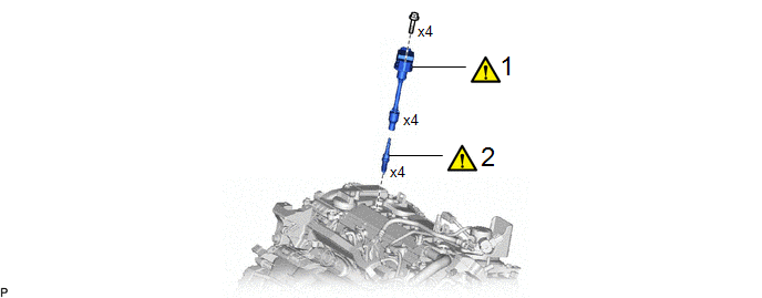
|
Procedure | Part Name Code |
.png) |
.png) |
 |
|---|---|---|---|---|---|
|
1 | IGNITION COIL ASSEMBLY |
19500 |
|
- | - |
|
2 | SPARK PLUG |
19100P |
|
- | - |
CAUTION / NOTICE / HINT
The necessary procedures (adjustment, calibration, initialization or registration) that must be performed after parts are removed and installed, or replaced during ignition coil assembly or spark plug removal/installation are shown below.
Necessary Procedures After Parts Removed/Installed/Replaced|
Replaced Part or Performed Procedure |
Necessary Procedure | Effect/Inoperative Function when Necessary Procedure not Performed |
Link |
|---|---|---|---|
| Inspection after repair |
|
|
NOTICE:
This procedure includes the removal of small-head bolts. Refer to Small-Head Bolts of Basic Repair Hint to identify the small-head bolts.
Click here .gif)
PROCEDURE
1. REMOVE IGNITION COIL ASSEMBLY
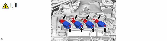
(1) Disconnect the 4 ignition coil assembly connectors.
(2) Using an 8 mm socket wrench, remove the 4 bolts and 4 ignition coil assemblies from the cylinder head cover sub-assembly.
NOTICE:
If an ignition coil assembly has been struck or dropped, replace it.
2. REMOVE SPARK PLUG
|
|
Click here |


