Toyota Corolla Cross: Wiper Module Missing Message (B235787)
DESCRIPTION
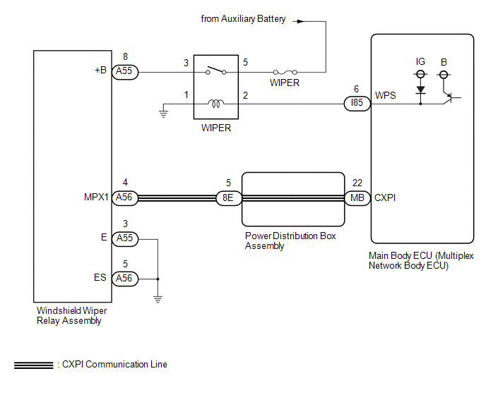
The main body ECU (multiplex network body ECU) and windshield wiper relay assembly communicate via CXPI communication. The main body ECU (multiplex network body ECU) stores this DTC if communication becomes abnormal.
|
DTC No. | Detection Item |
DTC Detection Condition | Trouble Area |
Memory | DTC Output from |
|---|---|---|---|---|---|
|
B235787 | Wiper Module Missing Message | Detection condition:
|
| ○ |
Main Body |
WIRING DIAGRAM
CAUTION / NOTICE / HINT
NOTICE:
- Inspect the fuses of circuits related to this system before performing the following procedure.
- Before replacing the main body ECU (multiplex network body ECU), refer to Registration.*1
- for HEV Model:
Click here
.gif)
- for Gasoline Model:
Click here
- *1: w/ Smart Key System
- for HEV Model:
PROCEDURE
|
1. | CHECK HARNESS AND CONNECTOR (WINDSHIELD WIPER RELAY ASSEMBLY - POWER DISTRIBUTION BOX ASSEMBLY) |
(a) Disconnect the A56 windshield wiper relay assembly connector.
(b) Disconnect the 8E power distribution box assembly connector.
(c) Measure the resistance according to the value(s) in the table below.
Standard Resistance:
|
Tester Connection | Condition |
Specified Condition |
|---|---|---|
|
A56-4 (MPX1) - 8E-5 | Always |
Below 1 Ω |
|
A56-4 (MPX1) or 8E-5 - Body ground |
Always | 10 kΩ or higher |
| NG | .gif) | REPAIR OR REPLACE HARNESS OR CONNECTOR |
|
.gif)
| 2. |
CHECK HARNESS AND CONNECTOR (POWER DISTRIBUTION BOX ASSEMBLY - MAIN BODY ECU (MULTIPLEX NETWORK BODY ECU)) |
(a) Disconnect the MB main body ECU (multiplex network body ECU) connector.
(b) Measure the resistance according to the value(s) in the table below.
Standard Resistance:
|
Tester Connection | Condition |
Specified Condition |
|---|---|---|
|
8E-5 - MB-22 (CXPI) | Always |
Below 1 Ω |
|
8E-5 or MB-22 (CXPI) - Body ground |
Always | 10 kΩ or higher |
| NG | | REPLACE POWER DISTRIBUTION BOX ASSEMBLY |
|
| 3. |
CHECK MAIN BODY ECU (MULTIPLEX NETWORK BODY ECU) |
|
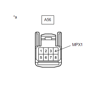
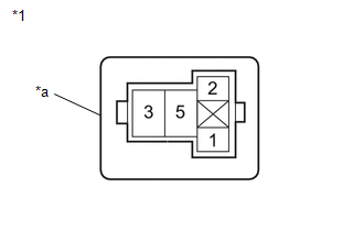
*a | Front view of wire harness connector (to Windshield Wiper Relay Assembly) |
(a) Connect the 8E power distribution box assembly connector
(b) Check for voltage and pulses according to the value(s) in the table below.
Standard Voltage:
|
Tester Connection | Switch Condition |
Specified Condition |
|---|---|---|
|
A56-4 (MPX1) - Body ground |
Ignition switch ON | Pulse generation |
|
A56-4 (MPX1) - Body ground |
Ignition switch off | 11 to 14 V |
| NG | | REPLACE MAIN BODY ECU (MULTIPLEX NETWORK BODY ECU) |
|
| 4. |
PERFORM ACTIVE TEST USING GTS (WIPER POWER RELAY) |
(a) Perform the Active Test according to the display on the GTS.
Body Electrical > Main Body > Active Test|
Tester Display | Measurement Item |
Control Range | Diagnostic Note |
|---|---|---|---|
|
Wiper Power Relay | Function to operate the WIPER relay |
OFF or ON | - |
|
Tester Display |
|---|
| Wiper Power Relay |
OK:
WIPER relay operates normally.
| NG | | GO TO STEP 10 |
|
| 5. |
CHECK HARNESS AND CONNECTOR (WINDSHIELD WIPER RELAY ASSEMBLY - BODY GROUND) |
(a) Disconnect the A55 and A56 windshield wiper relay assembly connectors.
(b) Measure the resistance according to the value(s) in the table below.
Standard Resistance:
|
Tester Connection | Condition |
Specified Condition |
|---|---|---|
|
A55-3 (E) - Body ground |
Always | Below 1 Ω |
|
A56-5 (ES) - Body ground |
Always | Below 1 Ω |
| NG | | REPAIR OR REPLACE HARNESS OR CONNECTOR |
|
| 6. |
CHECK HARNESS AND CONNECTOR (POWER SOURCE - WINDSHIELD WIPER RELAY ASSEMBLY) |
|
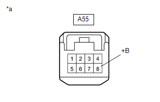
*a | Front view of wire harness connector (to Windshield Wiper Relay Assembly) |
(a) Measure the voltage according to the value(s) in the table below.
Standard Voltage:
|
Tester Connection | Switch Condition |
Specified Condition |
|---|---|---|
|
A55-8 (+B) - Body ground |
Ignition switch ON | 11 to 14 V |
|
Less than approximately 60 seconds after ignition switch turned off |
11 to 14 V | |
|
Approximately 60 seconds or more after ignition switch turned off |
Below 1 V |
| OK | | REPLACE WINDSHIELD WIPER RELAY ASSEMBLY |
|
| 7. |
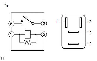
INSPECT WIPER RELAY |
(a) Remove the WIPER relay.
| (b) Measure the resistance according to the value(s) in the table below. Standard Resistance:
|
|
| NG | | REPLACE WIPER RELAY |
|
| 8. |
CHECK HARNESS AND CONNECTOR (POWER SOURCE - WIPER RELAY) |
| (a) Measure the voltage according to the value(s) in the table below. Standard Voltage:
|
|
| NG | | REPAIR OR REPLACE HARNESS OR CONNECTOR |
|
| 9. |
CHECK HARNESS AND CONNECTOR (WINDSHIELD WIPER RELAY ASSEMBLY - WIPER RELAY) |
(a) Measure the resistance according to the value(s) in the table below.
Standard Resistance:
|
Tester Connection | Condition |
Specified Condition |
|---|---|---|
|
A55-8 (+B) - WIPER relay holder terminal 3 |
Always | Below 1 Ω |
|
A55-8 (+B) - Body ground |
Always | 10 kΩ or higher |
| OK | | REPLACE MAIN BODY ECU (MULTIPLEX NETWORK BODY ECU) |
| NG | | REPAIR OR REPLACE HARNESS OR CONNECTOR |
| 10. |
INSPECT WIPER RELAY |
(a) Remove the WIPER relay.
| (b) Measure the resistance according to the value(s) in the table below. Standard Resistance:
|
|
| NG | | REPLACE WIPER RELAY |
|
| 11. |
CHECK HARNESS AND CONNECTOR (WIPER RELAY - MAIN BODY ECU (MULTIPLEX NETWORK BODY ECU)) |
(a) Disconnect the I85 main body ECU (multiplex network body ECU) connector.
(b) Measure the resistance according to the value(s) in the table below.
Standard Resistance:
|
Tester Connection | Condition |
Specified Condition |
|---|---|---|
|
WIPER relay holder terminal 2 - I85-6 (WPS) |
Always | Below 1 Ω |
|
WIPER relay holder terminal 2 or I85-6 (WPS) - Body ground |
Always | 10 kΩ or higher |
| NG | | REPAIR OR REPLACE HARNESS OR CONNECTOR |
|
| 12. |
CHECK HARNESS AND CONNECTOR (BODY GROUND - WIPER RELAY) |
| (a) Measure the voltage according to the value(s) in the table below. Standard Resistance:
|
|
| OK | | REPLACE MAIN BODY ECU (MULTIPLEX NETWORK BODY ECU) |
| NG | | REPAIR OR REPLACE HARNESS OR CONNECTOR |


