Toyota Corolla Cross: Front Wiper Motor Circuit
DESCRIPTION
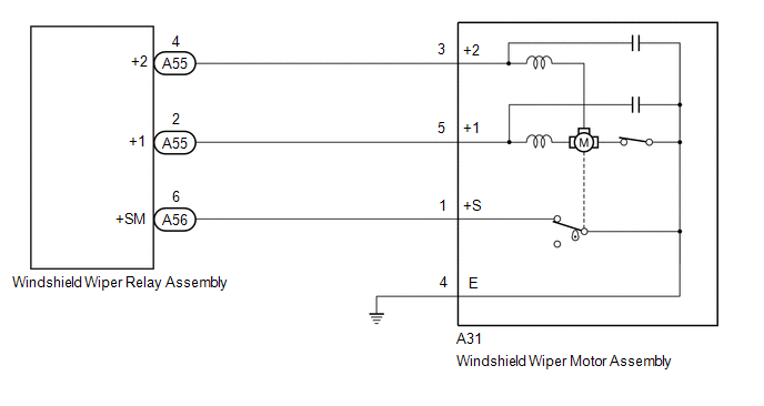
The windshield wiper relay assembly controls the windshield wiper motor assembly through this circuit.
WIRING DIAGRAM
PROCEDURE
| 1. |
PERFORM ACTIVE TEST USING GTS (FRONT WIPER LO OPERATION / FRONT WIPER HI OPERATION) |
(a) Perform the Active Test according to the display on the GTS.
Body Electrical > Main Body > Active Test|
Tester Display | Measurement Item |
Control Range | Diagnostic Note |
|---|---|---|---|
|
Front Wiper Lo Operation |
Function to operate the windshield wiper motor assembly in LO |
OFF or ON | - |
|
Front Wiper Hi Operation |
Function to operate the windshield wiper motor assembly in HI |
OFF or ON | - |
|
Tester Display |
|---|
| Front Wiper Lo Operation |
|
Tester Display |
|---|
| Front Wiper Hi Operation |
OK:
Windshield wiper motor assembly operates normally.
| OK | .gif) | PROCEED TO NEXT SUSPECTED AREA SHOWN IN PROBLEM SYMPTOMS TABLE
|
|
.gif)
| 2. |
INSPECT WINDSHIELD WIPER MOTOR ASSEMBLY |
Click here .gif)
| NG | | REPLACE WINDSHIELD WIPER MOTOR ASSEMBLY |
|
| 3. |
CHECK HARNESS AND CONNECTOR (WINDSHIELD WIPER RELAY ASSEMBLY - WINDSHIELD WIPER MOTOR ASSEMBLY) |
(a) Disconnect the A55 and A56 windshield wiper relay assembly connectors.
(b) Measure the resistance according to the value(s) in the table below.
Standard Resistance:
|
Tester Connection | Condition |
Specified Condition |
|---|---|---|
|
A55-2 (+1) - A31-5 (+1) |
Always | Below 1 Ω |
|
A55-4 (+2) - A31-3 (+2) |
Always | Below 1 Ω |
|
A56-6 (+SM) - A31-1 (+S) |
Always | Below 1 Ω |
|
A55-2 (+1) or A31-5 (+1) - Body ground |
Always | 10 kΩ or higher |
|
A55-4 (+2) or A31-3 (+2) - Body ground |
Always | 10 kΩ or higher |
|
A56-6 (+SM) or A31-1 (+S) - Body ground |
Always | 10 kΩ or higher |
| NG | | REPAIR OR REPLACE HARNESS OR CONNECTOR |
|
| 4. |
CHECK HARNESS AND CONNECTOR (WINDSHIELD WIPER MOTOR ASSEMBLY - BODY GROUND) |
(a) Measure the resistance according to the value(s) in the table below.
Standard Resistance:
|
Tester Connection | Condition |
Specified Condition |
|---|---|---|
|
A31-4 (E) - Body ground |
Always | Below 1 Ω |
| OK | | REPLACE WINDSHIELD WIPER RELAY ASSEMBLY
|
| NG | | REPAIR OR REPLACE HARNESS OR CONNECTOR |


