Toyota Corolla Cross: Wiper and Washer Switch Circuit
DESCRIPTION
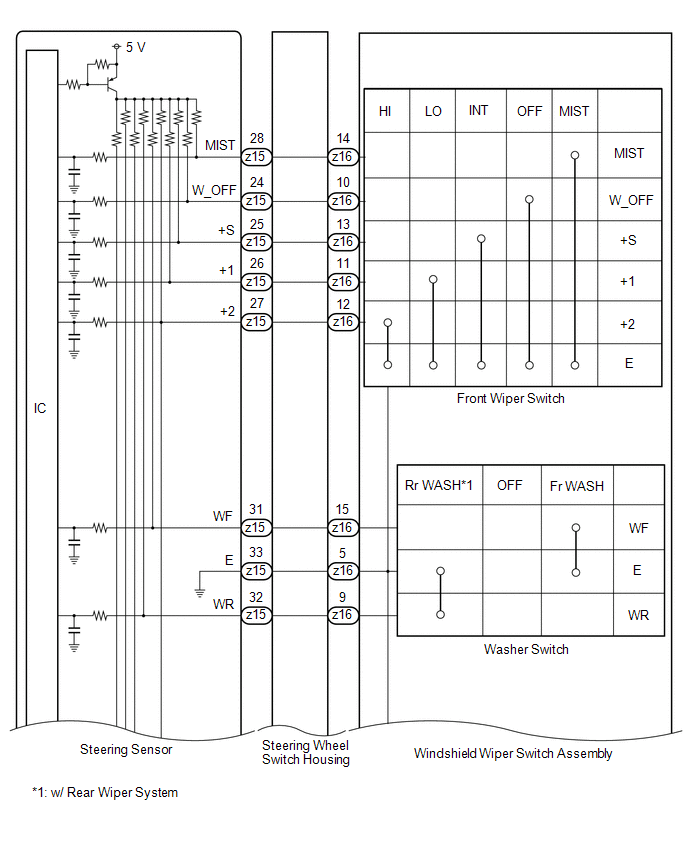
The condition of the windshield wiper switch assembly is detected and sent to the steering sensor in this circuit.
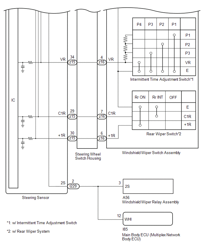
WIRING DIAGRAM
PROCEDURE
| 1. |
READ VALUE USING GTS (STEERING ANGLE SENSOR) |
(a) Read the Data List according to the display on the GTS.
Chassis > Steering Angle Sensor > Data List|
Tester Display | Measurement Item |
Range | Normal Condition |
Diagnostic Note |
|---|---|---|---|---|
|
Wiper OFF Switch | Front wiper switch OFF position signal |
OFF or ON | OFF: Front wiper switch not in OFF position ON: Front wiper switch in OFF position |
- |
| Wiper Auto/Int Switch |
Front wiper switch INT position signal |
OFF or ON | OFF: Front wiper switch not in INT position ON: Front wiper switch in INT position |
- |
| Wiper Lo Switch |
Front wiper switch LO position signal |
OFF or ON | OFF: Front wiper switch not in LO position ON: Front wiper switch in LO position |
- |
| Wiper Hi Switch |
Front wiper switch HI position signal |
OFF or ON | OFF: Front wiper switch not in HI position ON: Front wiper switch in HI position |
- |
| Wiper Mist Switch |
Front wiper switch MIST position signal |
OFF or ON | OFF: Front wiper switch not in MIST position ON: Front wiper switch in MIST position |
- |
| Washer Switch |
Washer switch Fr WASH position signal |
OFF or ON | OFF: Washer switch not in Fr WASH position ON: Washer switch in Fr WASH position |
- |
| Rear Wiper INT Switch |
Rear wiper switch Rr INT position signal |
OFF or ON | OFF: Rear wiper switch not in Rr ON position ON: Rear wiper switch in Rr ON position |
*1 |
| Rear Wiper ON Switch |
Rear wiper switch Rr ON position signal |
OFF or ON | OFF: Rear wiper switch not in Rr ON position ON: Rear wiper switch in Rr ON position |
*1 |
| Rear Washer Switch |
Washer switch Rr WASH position signal |
OFF or ON | OFF: Washer switch not in Rr WASH position ON: Washer switch in Rr WASH position |
*1 |
| Intermittent Time Volume (Shortest) |
Intermittent time adjustment switch condition |
Shortest | Shortest: P4 |
*2, *3 |
| Intermittent Time Volume (Shorter) |
Intermittent time adjustment switch condition |
Shorter | Shorter: P3 |
*2,*3 |
| Intermittent Time Volume (Longer) |
Intermittent time adjustment switch condition |
Longer | Longer: P2 |
*2,*3 |
| Intermittent Time Volume (Longest) |
Intermittent time adjustment switch condition |
Longest | Longest: P1 |
*2,*3 |
- *1: w/ Rear Wiper System
- *2: w/ Intermittent Time Adjustment Switch
- *3: Refer to Inspection for each position of the switch.
Click here
.gif)
|
Tester Display |
|---|
| Wiper OFF Switch |
|
Wiper Auto/Int Switch |
|
Wiper Lo Switch |
|
Wiper Hi Switch |
|
Wiper Mist Switch |
|
Washer Switch |
|
Rear Wiper INT Switch |
|
Rear Wiper ON Switch |
|
Rear Washer Switch |
|
Intermittent Time Volume (Shortest) |
|
Intermittent Time Volume (Shorter) |
|
Intermittent Time Volume (Longer) |
|
Intermittent Time Volume (Longest) |
OK:
The GTS display changes correctly in response to the windshield wiper switch assembly operation.
| OK | .gif) | PROCEED TO NEXT SUSPECTED AREA SHOWN IN PROBLEM SYMPTOMS TABLE
|
|
.gif)
| 2. |
INSPECT WINDSHIELD WIPER SWITCH ASSEMBLY |
Click here
| NG | | REPLACE WINDSHIELD WIPER SWITCH ASSEMBLY |
|
| 3. |
INSPECT STEERING WHEEL SWITCH HOUSING |
Click here
| NG | | REPLACE STEERING WHEEL SWITCH HOUSING
|
|
| 4. |
CHECK HARNESS AND CONNECTOR (STEERING SENSOR - WINDSHIELD WIPER RELAY ASSEMBLY) |
(a) Disconnect the A56 windshield wiper relay assembly connector.
(b) Disconnect the I85 main body ECU (multiplex network body ECU) connector.
(c) Measure the resistance according to the value(s) in the table below.
Standard Resistance:
|
Tester Connection | Condition |
Specified Condition |
|---|---|---|
|
I229-2 (2S) - A56-3 (2S) |
Always | Below 1 Ω |
|
I229-2 (2S) or A56-3 (2S) - Body ground |
Always | 10 kΩ or higher |
|
I229-2 (2S) - I85-12 (WHI) |
Always | Below 1 Ω |
|
I229-2 (2S) or I85-12 (WHI) - Body ground |
Always | 10 kΩ or higher |
| NG | | REPAIR OR REPLACE HARNESS OR CONNECTOR |
|
| 5. |
CHECK HARNESS AND CONNECTOR (WINDSHIELD WIPER RELAY ASSEMBLY) |
(a) Connect the A56 windshield wiper relay assembly connector.
(b) Measure the resistance according to the value(s) in the table below.
Standard Resistance:
|
Tester Connection | Condition |
Specified Condition |
|---|---|---|
|
I229-2 (2S) - Body ground |
Always | 10 kΩ or higher |
| NG | | REPLACE WINDSHIELD WIPER RELAY ASSEMBLY
|
|
| 6. |
CHECK MAIN BODY ECU (MULTIPLEX NETWORK BODY ECU) |
(a) Disconnect the A56 windshield wiper relay assembly connector.
(b) Connect the I85 main body ECU (multiplex network body ECU) connector.
(c) Measure the resistance according to the value(s) in the table below.
Standard Resistance:
|
Tester Connection | Condition |
Specified Condition |
|---|---|---|
|
I229-2 (2S) - Body ground |
Always | 10 kΩ or higher |
| OK | | REPLACE STEERING SENSOR
|
| NG | | REPLACE MAIN BODY ECU (MULTIPLEX NETWORK BODY ECU)
|


