Toyota Corolla Cross: Washer Motor Circuit
DESCRIPTION
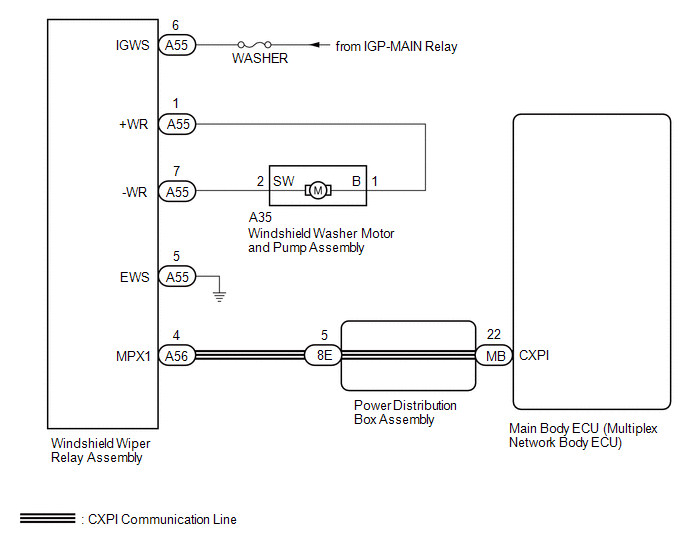
When the windshield washer motor and pump assembly receives signals from the windshield wiper switch assembly, it operates to spray washer fluid from the washer nozzle sub-assemblies.
WIRING DIAGRAM
CAUTION / NOTICE / HINT
NOTICE:
- Inspect the fuses of circuits related to this system before performing the following procedure.
- Before replacing the main body ECU (multiplex network body ECU), refer to Registration.*1
- for HEV Model:
Click here
.gif)
- for Gasoline Model:
Click here
- *1: w/ Smart Key System
- for HEV Model:
PROCEDURE
|
1. | PERFORM ACTIVE TEST USING GTS (FRONT WASHER RELAY / REAR WASHER RELAY) |
(a) Perform the Active Test according to the display on the GTS.
Body Electrical > Main Body > Active Test|
Tester Display | Measurement Item |
Control Range | Diagnostic Note |
|---|---|---|---|
|
Front Washer Relay | Function to operate the windshield washer motor and pump assembly (Front) |
OFF or ON | - |
|
Rear Washer Relay | Function to operate the windshield washer motor and pump assembly (Rear) |
OFF or ON | - |
|
Tester Display |
|---|
| Front Washer Relay |
|
Tester Display |
|---|
| Rear Washer Relay |
OK:
Windshield washer motor and pump assembly operates normally.
| OK | .gif) | PROCEED TO NEXT SUSPECTED AREA SHOWN IN PROBLEM SYMPTOMS TABLE |
|
.gif)
| 2. |
INSPECT WINDSHIELD WASHER MOTOR AND PUMP ASSEMBLY |
Click here
| NG | | REPLACE WINDSHIELD WASHER MOTOR AND PUMP ASSEMBLY |
|
| 3. |
CHECK HARNESS AND CONNECTOR (POWER SOURCE - WINDSHIELD WIPER RELAY ASSEMBLY) |
|
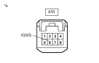
*a | Front view of wire harness connector (to Windshield Wiper Relay Assembly) |
(a) Disconnect the A55 windshield wiper relay assembly connector.
(b) Measure the voltage according to the value(s) in the table below.
Standard Voltage:
|
Tester Connection | Switch Condition |
Specified Condition |
|---|---|---|
|
A55-6 (IGWS) - Body ground |
Ignition switch ON | 11 to 14 V |
| NG | | REPAIR OR REPLACE HARNESS OR CONNECTOR |
|
| 4. |
CHECK HARNESS AND CONNECTOR (WINDSHIELD WIPER RELAY ASSEMBLY - BODY GROUND) |
(a) Measure the resistance according to the value(s) in the table below.
Standard Resistance:
|
Tester Connection | Condition |
Specified Condition |
|---|---|---|
|
A55-5 (EWS) - Body ground |
Always | Below 1 Ω |
| NG | | REPAIR OR REPLACE HARNESS OR CONNECTOR |
|
| 5. |
CHECK HARNESS AND CONNECTOR (WINDSHIELD WIPER RELAY ASSEMBLY - WINDSHIELD WASHER MOTOR AND PUMP ASSEMBLY) |
(a) Measure the resistance according to the value(s) in the table below.
Standard Resistance:
|
Tester Connection | Condition |
Specified Condition |
|---|---|---|
|
A55-1 (+WR) - A35-1 (B) |
Always | Below 1 Ω |
|
A55-7 (-WR) - A35-2 (SW) |
Always | Below 1 Ω |
|
A55-1 (+WR) or A35-1 (B) - Body ground |
Always | 10 kΩ or higher |
|
A55-7 (-WR) or A35-2 (SW) - Body ground |
Always | 10 kΩ or higher |
| OK | | REPLACE WINDSHIELD WIPER RELAY ASSEMBLY |
| NG | | REPAIR OR REPLACE HARNESS OR CONNECTOR |


