Toyota Corolla Cross: Transmission Wire
Removal
REMOVAL
CAUTION / NOTICE / HINT
COMPONENTS (REMOVAL)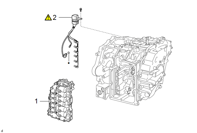
|
Procedure |
Part Name Code |
.png) |
.png) |
.png) |
|
|---|---|---|---|---|---|
|
1 |
TRANSMISSION VALVE BODY ASSEMBLY |
35410J |
- |
- |
- |
|
2 |
TRANSMISSION WIRE |
82125M |
|
- |
- |
|
● |
Non-reusable part |
- |
- |
CAUTION / NOTICE / HINT
The necessary procedures (adjustment, calibration, initialization, or registration) that must be performed after parts are removed and installed, or replaced during the transmission wire removal/installation are shown below.
Necessary Procedure After Parts Removed/Installed/Replaced|
Replacement Part or Procedure |
Necessary Procedures |
Effect/Inoperative Function When Necessary Procedures are not Performed |
Link |
|---|---|---|---|
|
CVT fluid |
ATF thermal degradation estimate reset |
The value of the Data List item "ATF Thermal Degradation Estimate" is not estimated correctly |
|
|
Bleed air from oil pump (continuously variable transaxle assembly) |
Stop and start system |
|
PROCEDURE
1. REMOVE TRANSMISSION VALVE BODY ASSEMBLY
Click here .gif)
2. REMOVE TRANSMISSION WIRE
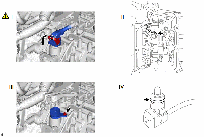
(1) Disengage the claw, rotate the lever and disconnect the connector.
(2) Disconnect the connector.
(3) Remove the bolt and transmission wire from the transaxle case sub-assembly.
(4) Remove the O-ring from the temperature sensor.
Installation
INSTALLATION
CAUTION / NOTICE / HINT
COMPONENTS (INSTALLATION)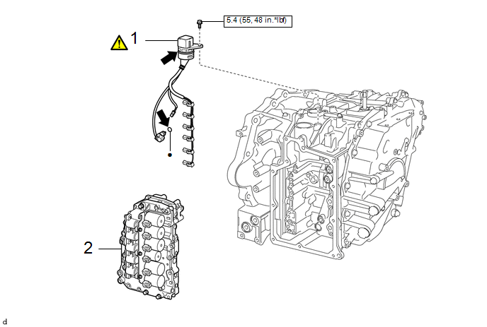
|
Procedure |
Part Name Code |
.png) |
.png) |
.png) |
|
|---|---|---|---|---|---|
|
1 |
TRANSMISSION WIRE |
82125M |
|
- |
- |
|
2 |
TRANSMISSION VALVE BODY ASSEMBLY |
35410J |
- |
- |
- |
.png) |
N*m (kgf*cm, ft.*lbf): Specified torque |
● |
Non-reusable part |
.png) |
Toyota Genuine CVT Fluid FE |
- |
- |
PROCEDURE
1. INSTALL TRANSMISSION WIRE
|
|
Toyota Genuine CVT Fluid FE |
- |
- |
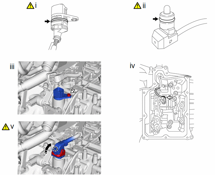
(1) Coat the O-ring of the transmission wire with Toyota Genuine CVT fluid FE.
NOTICE:
If reusing the transmission wire, check that the O-ring is not damaged.
(2) Coat a new O-ring with Toyota Genuine CVT fluid FE and install it to the temperature sensor.
NOTICE:
Ensure that the O-ring is not twisted.
(3) Install the transmission wire to the transaxle case sub-assembly with the bolt.
Torque:
5.4 N·m {55 kgf·cm, 48 in·lbf}
(4) Connect the connector.
(5) Connect the connector and rotate the lever and engage the claw.
NOTICE:
Rotate the lever until the claw of the connector makes a click sound.
2. INSTALL TRANSMISSION VALVE BODY ASSEMBLY
Click here .gif)


